4.2 Function
Chapter navigation
ECLASS ADVANCED enables the description of the functional structure of each product. Each product is broken down into its functions and these are described individually.
Products whose functional structures or connections vary depending on the configuration can also be displayed. This is done using function groups that represent the variations. The functions are only described within this upstream function group structure.
Preliminary mapping of functions that will be adapted in future versions.
Features functional group
Level | Species | Structure item Name | Application, meaning | Function for CAx and process |
|---|---|---|---|---|
1 | B | Functional group | Block Functional group | Block for describing the function group |
2 | M | Function criterion | Specification of the functional group description - scope of functions | Selection option for the CAx systems |
3 | W | Configuration Article | Identification of descriptions for the configuration of articles |
|
3 | W | Function group configuration | Identification of descriptions for the configuration of function groups |
|
3 | W | General configuration | Identification of general configuration and functional description of the article |
|
3 | W | Single function configuration | Identification of descriptions for the configuration of individual functions |
|
3 | W | Assembly | Identification of descriptions of assembly configurations |
|
2 | M | Functional group execution | Textual reference | Possibility to specify application notes |
2 | M | Type of functional groups | Description of the type of function group | Application identifier for the directly subordinate function groups |
3 | W | fixed functional groups | With this value, all subordinate function groups are an integral part of the product. Direct assignment to function group no selection | The function groups are permanently assigned to the product |
3 | W | Variants of function groups | With this value only one of the subordinate function groups is part of the configured product. Variant Assignment to function group. A selection is required | Selection of a possible variant during the project engineering process |
2 | C | Number of function groups | Identification of the number of existing function groups | Calls the block for describing a function group recursively according to number |
2/3 | B | Function group | Block Functional group | Possibility to describe configuration-dependent variants |
2 | C | Number of part-relationships | Only if, depending on the function group, different parts are required than those already defined at the part level. For further information see point 3.1 Parts Relations | Calls the block for part reference description according to quantity. Here configuration-dependent parts can be assigned to the product |
2 | C | Number of functions | Indication of the number of available functions of the article within this function group Further see point 4.2 Function#Function | Calls up the block for functional description according to the number |
Function
Level | Species | Structure item Name | Application, meaning | Function for CAx and process |
|---|---|---|---|---|
1 | B | Function | Block Function | Block for describing the function |
2 | C | Number of part-relationships | Only if, depending on the function, different parts are required than those already defined at the article level under part relationship. Further see point 3.1 Parts Relations | Calls the block for part reference description according to quantity |
2 | C | Number of functional relationships | identification of the number of existing functional relationships of the article | Calls the block for the function relationship description according to number |
2/3 | B | Functional relationship | Block Functional relationship | Block for describing the functional relationship |
4 | M | Functional relationship criterion | Description of the dependency of the function to the article |
|
5 | W | Depending on configuration | Identification of the function relationship as configuration-dependent |
|
5 | W | fixed relationship | Identification of the functional relationship as fixed |
|
4 | M | Function name | Identification of the assigned function to the function relationship |
|
2 | B | Function identification | Block Function identification | Block for describing the function identification. For further information see |
3 | M | Function description | Textual note (long) | Long text for project engineering support |
3 | M | Function designation | Currently eClass Symbol ID function identification or, if not possible, short text for supporting identification of the function. Is shown more frequently in CAE. (Ex: DI for identification of a digital input channel) | Currently ID as reference to the symbol or as a mapping reference |
3 | M | Function name | Identifier of the function. Is e.g. represented in CAE, for example, in structures, lists and graphical symbols. Example: CH1 for channel 1, see 4.2 Function#Electrical connections | Supports functional project planning |
3 | M | Code letter according to task/purpose of the subclass (IEC 81346-2) | Further see 3 CAx-Basis Aspect | Is required by the CAx systems for function-oriented plant modelling. |
3 | M | Code letter according to task/purpose of the class (IEC 81346-2) | Further see 3 CAx-Basis Aspect | Is required by the CAx systems for function-oriented plant modelling. |
2 | B | Device or connection | Block Device or connection | Calls the block for device or connection description |
3 | P | Type of function | Call type of the function polymorph. Identification of the article as a device or connection
| For the CAx documentation, a distinction is made between the objects device and connection, as these are described with different properties |
4 | W |
Device
| Identification of the polymorphic block device Is selected if the article has functions that are connected to other articles via connections or wireless communication interfaces
| Calls features to describe device functions. For further details see description of device 4.2 Function#Device |
4 | W | Connection | Identification of the polymorphic block connection Is selected if the article can connect 2 connections between two objects
| Calls features to describe connection functions. For further details see description 4.2 Function#Connection |
Device
To represent mechatronic devices and their combinations, functions can be described differently according to their technical disciplines. This is implemented using the feature Type of the device.
In the electrical function group, information is provided on the product properties for function-oriented engineering from the perspective of CAE planning for automation systems.
Level | Species | Structure item Name | Application,meaning | Function for CAx and process |
|---|---|---|---|---|
1 | W | Device | Identification of the polymorphic block Device | See: 4.2 Function#Function Characteristic Type of Function Value: Device |
2 | C | Number of device connections | Specification of the number of assigned device connections for the function | Calls the block for describing device connections according to number. Further see 4.2 Function#Device connection |
2
| C | Number of device plugs | Specification of the number of assigned device plugs for the function | Calls up the block for describing device connection according to number Continue see 4.2 Function#Device plug |
2 | P | Type of the device | Call Type of the device polymorphic | Selection Type of device |
3 | W | Device function (electrical) | Identification of the polymorphic block Device function (electrical) |
|
4 | P | Function group (electrical) | Call function group (electrical) polymorphic |
|
5 | W | Central function | Identification of the polymorphic block Central function | Further see 4.2 Function#Device#Central function |
5 | W | Communication interface | Identification of the polymorphic block Communication interface | Futher see 4.2 Function#Device#Communication interface |
5 | W | Contact | Identification of the polymorphic block contact | Further see 4.2 Function#Device#Contact |
5 | W | Electromechanical drive | Identification of the polymorphic block electromechanical drive | Further see 4.2 Function#Device#Electromechanical drive |
5 | W | Input/output | Identification of the polymorphic block input/output | Further See 4.2 Function#Device#Input/output |
5 | W | Signal adjuster | Identification of the polymorphic block signal adjuster | Further see 4.2 Function#Device#Signal adjuster |
5 | W | Terminal/terminal level | Identification of the polymorphic block terminal/terminal level | This function represents the product itself. It is used to transfer structures such as connections for the product. This function may only be used once per product and for further information see 4.2 Function#Device#Terminal/terminal level |
3 | W | Device function (hydraulic) | Identification of the polymorphic block Equipment function (hydraulic) | Not yet modelled out |
3 | W | Device function (connector element) | Identification of the polymorphic block Device function (connector element) | Not yet modelled out |
3 | W | Device function (pneumatic) | Identification of the polymorphic block Device function (pneumatic) | Not yet modelled out |
3 | W | Device function (process engineering) | Identification of the polymorphic block Device function (procedural) | Not yet modelled out |
4 | C | Number of explosion protection parameters for intrinsic safety | Specification of the number of explosion protection parameters for intrinsic safety | Calls the block for the description of explosion protection parameters for intrinsic safety according to the number |
4/5 | B | Explosion protection parameters for intrinsic safety | Block Explosion protection parameters for intrinsic safety |
|
6 | M | Concept of explosion safety |
|
|
7 | W | Entity |
|
|
7 | W | FISCO |
|
|
7 | W | FNICO |
|
|
7 | W | non incendive |
|
|
7 | W | SISCO |
|
|
6 | M | Ignition protection type intrinsic safety |
|
|
6 | B | Safety-related parameter active |
|
|
7 | M | max. external capacity |
|
|
7 | M | max. external inductance |
|
|
7 | M | max. external inductance/resistance ratio |
|
|
7 | M | max. output current |
|
|
7 | M | max. output power |
|
|
7 | M | max. output voltage |
|
|
6 | B | Passive safety parameter |
|
|
7 | M | max. input power |
|
|
7 | M | max. input voltage |
|
|
7 | M | max. input current |
|
|
7 | M | max. internal capacity |
|
|
7 | M | max. inner inductance |
|
|
4 | C | Number of rated values of device functions | Specification of the number of existing rated values of the device functions | Calls the block for describing the rated values of the device functions according to the number |
4/5 | B | Rated value | Specification of design values for the function |
|
6 | M | Device circuit technology |
|
|
6 | M | Power factor (Cos phi) |
|
|
6 | M | Rated current |
|
|
6 | M | Rated frequency |
|
|
6 | M | Rated power (AC) |
|
|
6 | M | Rated power (DC) |
|
|
6 | M | Rated voltage |
|
|
6 | M | Rated voltage form |
|
|
4 | C | Number of galvanic separations | Specification of the number of galvanic isolations | Calls the block for the description of the galvanic isolation according to the number |
4/5 | B | Galvanic isolation | Block galvanic isolation |
|
6 | M | galvanic isolation from earthing | Specification of the test voltage | Description of the galvanic isolation for safe plant engineering required |
6 | M | galvanic isolation to outputs | Specification of the test voltage | ditto |
6 | M | galvanic isolation to communication interfaces | Specification of the test voltage | ditto |
6 | M | galvanic isolation to external supplies | Specification of the test voltage | ditto |
6 | M | galvanic isolation to Test voltage inputs | Specification of the test voltage | ditto |
6 | M | galvanic isolation to internal supplies | Specification of the test voltage | ditto |
6 | M | Reference standard for galvanic isolation | Specification of the standard on which the galvanic isolation information is based | ditto |
4 | C | Number of explosion protection parameters for non-ignitable installations | Specification of the number of explosion protection parameters for non-ignitable installations | Calls up the block for the description of explosion protection parameters for non-ignitable installations according to the number |
4/5 | B | Explosion protection Device parameters for non-ignitable installation | Block Explosion protection Device parameters for non-ignitable installations | Required for project engineering of the Ex-protection |
6 | M | internal inductance | Resulting inductance at the electrical input or output of the device in mH | Required for project engineering of the Ex-protection |
6 | M | internal capacity | Resulting capacity at the electrical input or output of the device in μF | Required for project engineering of the Ex-protection |
6 | M | max. permissible voltage | max. permissible voltage below which the equipment may be operated | Required for project engineering of the Ex-protection |
Central function
This function represents the product itself. It is used to transfer structures such as connectors for the product. This function may only be used once per product and should always be used as the first function.
This selection of this function has no further features.
Communication interface
Level | Species | Structure item Name | Application, meaning | Function for CAx and process |
|---|---|---|---|---|
1 | M | Identification of the digital communication interface | Specification of the communication interface | Information is required for project engineering. |
2 | W | Value selection from a list |
| CAE relevant to presentation |
1 | M | Type of communication protocol | Specification of the communication protocol | Information is required for project engineering |
2 | W | Value selection from a list |
| CAE relevant to presentation |
1 | M | Interface design | Information on contacting | Information is required for project engineering. |
2 | W | Wireless |
| CAE relevant to presentation |
2 | W | Fixed connection |
| CAE relevant to presentation |
2 | W | Connector |
| CAE relevant to presentation |
Contact
Level | Species | Structure item Name | Application, meaning | Function for CAx and process |
|---|---|---|---|---|
1 | M | Switching function | Description of the contact function execution according to IEC 60617 | Information is required for project engineering |
2 | W | Auxiliary switch |
| CAE relevant to presentation |
2 | W | Switch-disconnector function |
| CAE relevant to presentation |
2 | W | Circuit breaker function |
| CAE relevant to presentation |
2 | W | Motor protection circuit breaker |
| CAE relevant to presentation |
2 | W | contactor function |
| CAE relevant to presentation |
2 | W | Disconnector function |
| CAE relevant to presentation |
1 | M | Type of contact | Information on the type of contact according to IEC 60617 | Information is required for project engineering |
2 | W | mechanical |
| CAE relevant to presentation |
2 | W | electronic |
| CAE relevant to presentation |
1 | M | Design of the contact | Specification of the switching function of the contact | Information is required for project engineering |
2 | W | make contact | The contact closes on excitation | CAE relevant to presentation |
2 | W | break contact | The contact opens on excitation | CAE relevant to presentation |
2 | W | change-over contact | The contact changes the switching positions on excitation | CAE relevant to presentation |
1 | M | Contact behaviour | Additional description of the contact behaviour according to IEC 60617. only if applicable | Information is required for project engineering |
2 | W | off-delayed | The contact switches with a time delay when de-excitation occurs | CAE relevant to presentation |
2 | W | on and off-delayed | The contact switches with a time delay on excitation and de-excitation | CAE relevant to presentation |
2 | W | On-delayed | The contact switches with a time delay when excited | CAE relevant to presentation |
2 | W | wiping off | When de-excited, the contact changes its switching position and then automatically returns to its initial position without any pending excitation | CAE relevant to presentation |
2 | W | wiping on and off | On energization, the contact changes its switching position and then automatically returns to its initial position despite the pending energization. And when de-energized, the contact changes its switching position and then automatically returns to its initial position without any pending energization | CAE relevant to presentation |
2 | W | wiping on | On excitation, the contact changes its switching position and then automatically returns to its initial position despite the excitation | CAE relevant to presentation |
2 | W | lagging | When excited, the contact switches after the main/normal contact | CAE relevant to presentation |
2 | W | leading | When excited, the contact switches before the main/normal contact | CAE relevant to presentation |
2 | W | Clock generator | When excited, the contact switches on and off according to the clock pulse | CAE relevant to presentation |
1 | M | Contact decline representation | Description of the contact regression representation according to IEC 60617. Only if necessary | Information is required for project engineering |
2 | W | without representation |
| CAE relevant to presentation |
2 | W | automatic tripping |
| CAE relevant to presentation |
2 | W | not automatic |
| CAE relevant to presentation |
1 | M | Actuation of the contact | Additional actuation indication if technically necessary | Information is required for project engineering |
2 | W | Limit switch |
| CAE relevant to presentation |
2 | W | under-voltage |
| CAE relevant to presentation |
2 | W | under-current |
| CAE relevant to presentation |
2 | W | automatic tripping |
| CAE relevant to presentation |
2 | W | automatic tripping |
| CAE relevant to presentation |
2 | W | thermal |
| CAE relevant to presentation |
2 | W | over-voltage |
| CAE relevant to presentation |
2 | W | over-current |
| CAE relevant to presentation |
2 | W | over-current and thermal |
| CAE relevant to presentation |
1 | M | Surface of contact | For contact safety or environmental resistance | This information is required for project planning under certain environmental conditions |
2 | W | Value selection from a list | like gold, silver, nickel | This information may be required for project engineering |
1 | M | Contact hysteresis | Possibility to specify if technically necessary Hysteresis of the trip value to prevent the contact from bouncing when returning to normal | This information is sometimes required for project planning |
Electromechanical drive
Level | Species | Structure item Name | Application, meaning | Function for CAx ans process |
|---|---|---|---|---|
1 | M | Execution of the function | Description of the function execution according to IEC 60617 | Information is required for project engineering |
2 | W | power on- and off-delay |
| CAE relevant to presentation |
2 | W | power on-delay |
| CAE relevant to presentation |
2 | W | Remanence relay |
| CAE relevant to presentation |
2 | W | Resonance relay |
| CAE relevant to presentation |
2 | W | Power off-delay |
| CAE relevant to presentation |
2 | W | Latching relay |
| CAE relevant to presentation |
2 | W | Thermal relay |
| CAE relevant to presentation |
2 | W | Alternating current relay |
| CAE relevant to presentation |
2 | W | general |
| CAE relevant to presentation |
2 | W | electronic |
| CAE relevant to presentation |
2 | W | electronic drive |
| CAE relevant to presentation |
2 | W | insensitive to alternating current |
| CAE relevant to presentation |
2 | W | polarizing |
| CAE relevant to presentation |
2 | W | quick-switching |
| CAE relevant to presentation |
2 | W | two separate windings |
| CAE relevant to presentation |
1 | M | Additional circuitry integrated | Specification of the type of an additional circuit for additive representation according to IEC 61617 | Information is required for project engineering |
2 | W | Diode |
| CAE relevant to presentation |
2 | W | RC element |
| CAE relevant to presentation |
2 | W | Varistor protection |
| CAE relevant to presentation |
1 | M | Function display | Indication of a mechanical or optical function indicator | Information is required for project engineering |
2 | W | Yes | Function display available | CAE relevant to presentation |
2 | W | no | no function display | CAE relevant to presentation |
Input/output
Level | Species | Structure item Name | Application, meaning | Function for CAx and process |
|---|---|---|---|---|
1 | M | Potential version | Text specification for potential assignment | CAx-representation and project engineering relevant String to describe the potential (e.g. 24V DC) |
1 | M | Contact potential | Description of the potential assignment of a contact output | For the output with switching contact, you can specify here which potential behavior is present |
2 | W | Potential | Indication of the possible potential | Potential-loaded means that a connection is active, i.e. it supplies a voltage itself |
2 | W | potential-free | Indication of the potential free | Potential-free means that the connections are passive, i.e. do not supply any voltage themselves |
1 | M | Control relevance | Description of the usability of the input and output by the higher-level automation system | Specification for project engineering support |
2 | W | Central control relevant | Specification of the usability by the higher-level automation system | CAx Project engineering relevant It is specified here whether the channel can also be addressed directly by the central controller (relevant to the central controller, e.g. channel of a sensor-actuator box) |
2 | W | Device relevant | Specification of usability only by the device | CAx project engineering relevant It is specified here whether the channel can only be addressed directly by the device. (Device relevant, e.g. channel to frequency inverter) |
1 | B | Signal description | Block Signal description | Description of the signal properties at the input or output |
2 | M | Type of signal | Short identification of the input and output type | CAx project engineering relevant Multivalent specification of the channel types
|
3 | W | DI | Digital input | CAx project engineering relevant |
3 | W | DO | Digital output | CAx project engineering relevant |
3 | W | AI | Analog input | CAx CAx project engineering relevant |
3 | W | AO | Analog output | CAx project engineering relevant. |
2 | M | Type of measurement | Description of the type of measurement for analog inputs | CAx project engineering relevant Indication of which signal is processed or generated for an analog channel |
3 | W | I | Current measurement | Relevant for project engineering |
3 | W | U | Voltage measurement | Relevant for project engineering |
3 | W | TC | Thermocouple measurement | Relevant for project engineering |
3 | W | RTD | Resistance thermometer measurement | Relevant for project engineering |
2 | M | Signal level | Description of the signal level for analog inputs and outputs | Information is required for project engineering |
2 | W | Value selection from a list | z.B. - +10…-10V … - 20-4 mA … - NAMUR | Multivalent indication of the possible signal levels of the analog channel (exception: NAMUR for digital channels) |
2 | M | Signal behaviour | Description of the signal behaviour Clarification of a required power supply | Information is required for project engineering |
3 | W | active/passive | Specifies that the signal can be set active or passive | Form of use must be agreed in the project engineering |
3 | W | active | Indication that the signal is active | Requires no external power supply |
3 | W | passive | Specifies that the signal is passive | Requires an external power supply |
Signal adjuster
The selection of this function has no further features.
Terminal/terminal level
The selection of this function has no further features.
Example: Through clamp
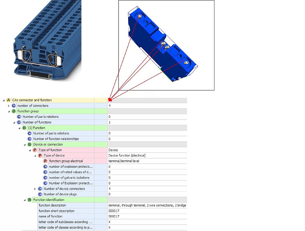
Figure 58: Example Number of connections
Example below:
Miniatur circuit breaker, 3p. described 12 real connections 1 function with 6 functional connections. Function identification with registered ECLASS number in the function designation.
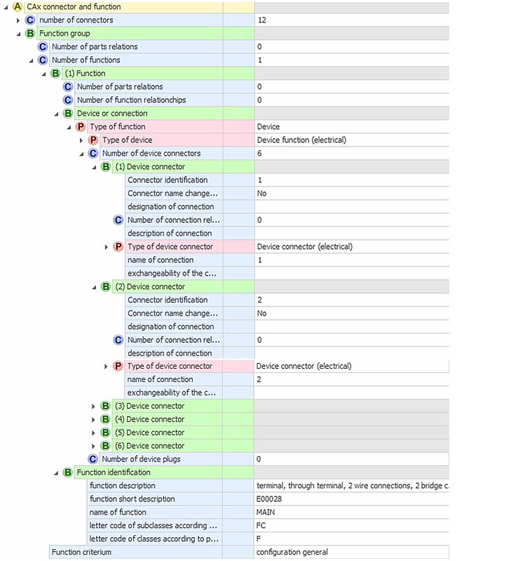
Figure 59: Example connections and functions
Connection
This chapter describes how connections (conductors, lines) are functionally described for use in a CAx documentation.
Level | Species | Structure item Name | Application, meaning | Function for CAx and process |
|---|---|---|---|---|
1 | W | Connection | Identification of the polymorphic block Connection | See: 4.2 Function#Function Characteristic Type of Function Value: Connection
|
2 | C | Number of connecting structures | Indication of the number of existing connection structures | Calls the block for the connection establishment description according to the number |
2/3 | B | Connection establishment | Block connection establishment | Block for connection establishment description e.g. cable structure |
4 | M | Fastener structure | Angabe über die Information about the arrangement structure of the connecting element e.g. cable | Enables the structure of cable to be described |
5 | W | Bundles with star quads |
|
|
5 | W | Bundle with conductors |
|
|
5 | W | Bundle with pairs |
|
|
5 | W | Star quad |
|
|
5 | W | twisted pair |
|
|
4 | C | Number of connecting structures | Description call hydraulic functions | As described above |
4 | B | Connection jacket | Block connecting jacket | Ability to describe the envelope of a joint |
5 | M | Sheathing material | Specification of the material of the sheathing | Is required for cable planning |
5 | M | Basic colour | Colour specification | Is required for correct cable selection |
5 | M | Diameter | Specification in mm | Is required for cable entry |
5 | M | Thickness | Specification in mm | Is required for cable entry |
4 | C | Number of connecting elements | Specification of the number of existing connection structures | As described above |
4/5 | B | Connecting element | Block connecting element | Block for connection element description e.g. conductor, shield, protection conductor |
6 | W | Connection name |
|
|
6 | W | Connection designation |
|
|
6 | W | Connection description |
|
|
6 | W | Basic colour |
|
|
6 | C | Number of partrelationships | Only if different parts are required depending on the fastener than those already defined at the article level under part relationship. Further see 3.1 Part Relations | Calls the block for part reference description according to quantity |
6 | P | Nature of the connection | Block call polymorphic | Connection-specific call of description blocks |
6/7 | W | electrical contact | Calls up features to describe an electrical connection | Block not available |
8 | M | Conductor cross section (AWG/KCMIL) | Specification of the conductor cross section according to American standards | Is required for circuit planning |
8 | M | Conductor cross section (mm²) | Specification of the conductor cross section according to IEC standards | Is required for circuit planning |
8 | M | conductor shape | Describes the profile shape of the conductor Values: concentric, rectangular, round, sectoral | Is required for connection planning |
8 | M | conductor construction | Information about the structure of the conductor. value list E.g. foil, fine-stranded | Is required for project planning and connection planning |
8 | M | Diameter of the conductor | Diameter in mm | For planning the fastening |
8 | M | Manager function | Functional assignment of the connecting element | Values: e.g. conductor, protective conductor shield, ... |
8 | M | Material of the core, material of the conductor | Specification Type of conductor material | Values: e.g. copper, aluminium,... |
8 | B | Electrical characteristics | Block electrical characteristics of the conductor | Block for describing the electrical characteristics of the conductor. Is required for project planning and selection |
9 | M | Nominal voltage U0 | specifies the effective value of the electrical voltage of the conductor between conductor and earth | Helps the system/designer to assign and arrange the conductor |
9 | M | Rated current | is the current that the conductor can carry in continuous operation | Helps the system/designer to assign and arrange the conductor |
9 | M | Rated voltage | specifies the maximum value of the electrical voltage between two conductors in normal operation | Helps the system/designer to assign and arrange the conductor |
9 | M | Rated insulation voltage | specifies the maximum value of the electrical voltage for the conductor | Helps the system/designer to assign and arrange the conductor |
1 | M | Surface of the contact | Security of Contact and Environmental resistance | Information is required for project planning in some environmental conditions |
6/7 | W | Optical fibrecable | Calls up features for the description of an optical waveguide | Block not available |
8 | C | Number of attenuation coefficients | Specification of the number of existing connection setups | Is required for the optical fiber cable planning |
8 | M | attenuation coefficient | Attenuation coefficient in dB/km | Is required for the optical fiber cable planning |
8 | M | Transmission wavelength | Transmission wavelength nm | Is required for the optical fiber cable planning |
8 | M | Core diameter of the fibre | Specification of diameter of fibre in μm | Is required for the optical fiber cable planning |
8 | M | Sheath diameter of the fibre | Sheath diameter of the fibre in μm | Is required for the optical fiber cable planning |
8 | M | Fibre | Specification of the type of optical fibre | Is required for the optical fiber cable planning. Values: e.g. GOF, PCF |
8 | M | Fibre type | Operating mode specification | Is required for the optical fiber cable planning. Values: e.g. Multimode |
8 | M | Numerical literature | Information on light focusing ability | Is required for the optical fiber cable planning |
8 | M | Material of the fibre sheath | Material specification for the fibre sheath | Is required for the optical fiber cable planning |
8 | M | Material of the fibre core | Material specification for the fibre core | Is required for the optical fiber cable planning |
8 | M | Protective coating of the fibre | Information on the protective coating directly on the fibre | Is required for the optical fiber cable planning |
8 | M | Number of transmission bandwidths | Specifies the number of possible transmission bandwidths | Is required for the optical fiber cable planning |
6/7 | W | hydraulic compound | Calls up characteristics to describe a hydraulic compound | Block not available |
6/7 | W | mechanical bonding | Calls up features to describe a mechanical connection | Block not available |
6/7 | W | optical link | Calls features to describe an optical connection | Block not available |
6/7 | W | pneumatic connection | Calls up features to describe a pneumatic connection | Block not available |
6/7 | W | Process engineering connections | Calls up characteristics for the description of a process engineering connection | Block not available |
4 | C | Number of shieldings | Specification of the number of existing shieldings | |
4/5 | B | Connecting element | Block connecting element | |
6 | C | Number of part-relationships | Only if different parts are required depending on the fastener than those already defined at the article level under part relationship. Further see 3.1 Parts Relations | Calls up the block for part reference description according to number |
6 | M | Connection description | As described above | |
6 | M | Connection name |
| As described above |
6 | M | Connection designation |
| As described above |
6 | M | Basic colour |
| As described above |
Examples of configurable device dependencies
These examples show the ECLASS-Advanced possibilities for describing configurable functions of a device for CAx purposes.
Example 1 Connection configuration of a module
Device:
Siemens S7-300 SM331, MLFB: 6ES7331-7KF02-0AB0
ECLASS class:
PLC analog input module; 27-24-22-01 (AKE524004)
Description:
- 8 analog inputs in 4 channel groups
- measurement type adjustable per channel group
- available measurement types: voltage, current, resistance, temperature
- adjustment via range module
- 2 channels are connected together for resistance measurement
With this device, several functional structures and connections depending on the configuration. The variations are represented by function groups. The configurable functions are then only described within the upstream function group structure. The configuration-independent functions are described on the top level (functions). See the following diagram:
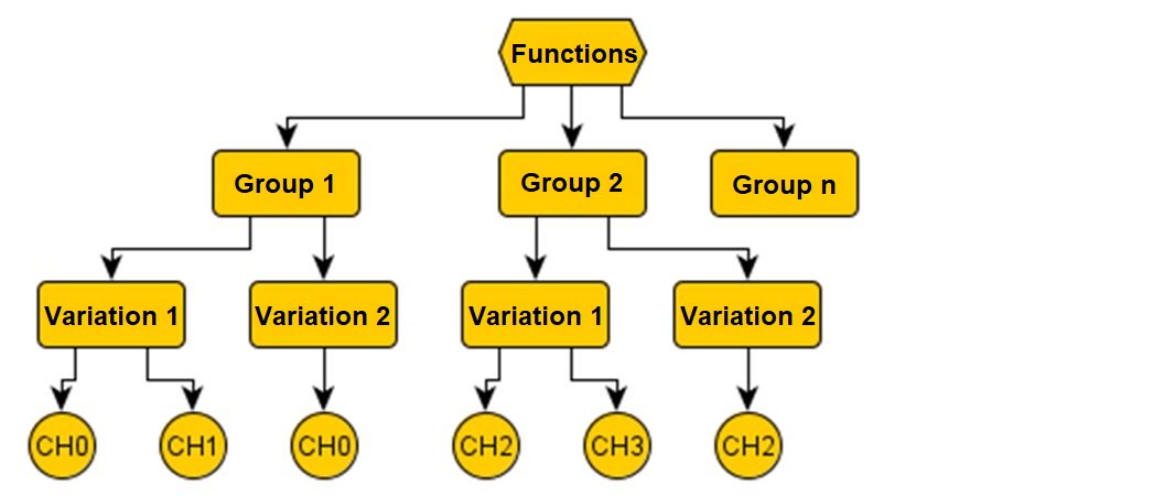
Figure 60: CAx example for configurable devices voltage and current measurement
The basic circuit diagrams of the module are shown below:
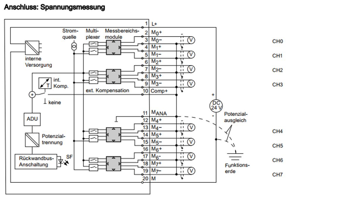
Figure 61: CAx example of configurable devices voltage and current measurement
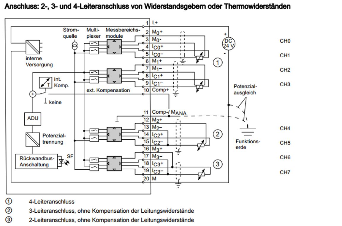
Figure 62: CAx example of configurable devices Resistance measurement
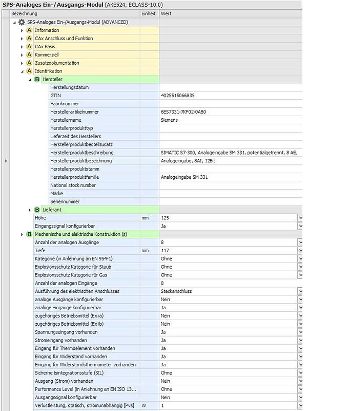
Figure 63: CAx example configurable device classified Base
Example Basic classification of the device:
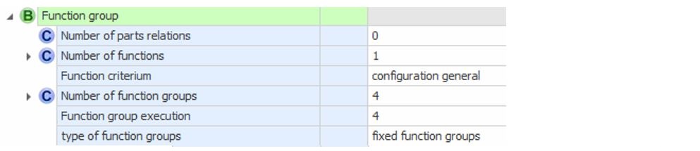
Figure 64: CAx example of configurable device Function group top level
Determination:
1 function 4 function groups
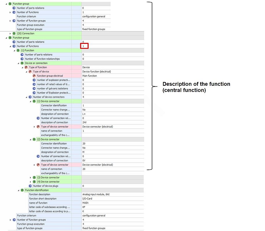
Figure 65: CAx example of configurable device Central function
Device connection
The following structure elements are available for the functional description of a connection.
Since the symbols used in the functional diagrams in the circuit diagram are only provided with one symbol connector, the connections for the function are only described once, even if further parallel real connections are described in the Connections section.
Level | Species | Structure item Name | Application, meaning | Function for CAx and process |
|---|---|---|---|---|
1 | B | Device connection | Call block Device connection | Block for device connection description |
2 | M | Connection identifier | Clear designation of a connection point (connection) | ID as reference to the description of the real connection |
2 | M | Port name | Alphanumeric identifier of a connection / PIN that indicates the function of the connection | Corresponds to the manufacturer-specific connection labelling, or if no labelling is available, the connection identifier |
2 | M | Port name changeable | Specifies whether the port name can be changed by the user | Example: The connection name is only a placeholder for a selectable label. Fixed manufacturer designations have priority |
2 | M | Exchangeability of the port name | Replace the connection with another one without changing the function. Specification of the connection names, enumeration separated by commas | Can be used to optimize wiring runs (looping) |
2 | M | Connection designation | For additional text information beyond the connection designation, see connection name. E.G. L+, I0 | For the specification of connection-related Text additions independent of the port name |
2 | M | Connection description | Additional explanatory long text that describes the connection |
|
2 | C | Number of connection relationships | Specification of the number of assigned connection relationships to the function | Calls the block for the connection relationship description according to number |
2/3 | B | Connection relationship | Call block connection relationship | Connection relationship description block |
4 | M | Connection name | Name of a connection | Possibility to name required connections (cables, wires to other components e.g. W1 |
4 | M | Function name | Name of a function | Possibility of naming the function |
2 | P | Type of device connection |
|
|
3 | W | device connection (hydraulic) |
| Calls up description block implement connection (hydraulic). Intended extension. No specific features and structures are currently defined. However, the type itself can be used. |
3 | W | Device connection (mechanical) |
| Calls description block Device connection (mechanical). Intended extension. Currently inactive No specific features and structures are currently defined. However, the type itself can be used. |
3 | W | Device connection (optical) |
| Calls description block Device connection (mechanical). Intended extension. Currently inactive No specific features and structures are currently defined. However, the type itself can be used. |
3 | W | Device connection (pneumatic) |
| Calls description block device connection (pneumatic). No specific features and structures are currently defined. However, the type itself can be used. |
3 | W | Device connection (procedural) |
| Calls description block Device connection (procedural). No specific features and structures are currently defined. However, the type itself can be used. |
3 | W | Device connector plug |
| Calls up the description block Device connector plug (poly medium). Intended extension. Currently inactive |
3 | W | Device connection (electrical) |
| Calls up description block Device connection (electrical) for connection function, potential and equivalencies |
4 | B | Connecting function, potential and equivalencies | Block for describing the connection function, potential and equivalencies | Enables a machine-readable potential description |
5 | M | Connecting function (electrical) | Describes the assignment of the connection to the CAx functions of the equipment | Values: |
6 | W | Collector |
|
|
6 | W | common contact |
|
|
6 | W | Break contact |
|
|
6 | W | Make contact |
|
|
6 | W | Drain |
|
|
6 | W | GND |
|
|
6 | W | Emitter |
|
|
6 | W | Load input |
|
|
6 | W | Load output |
|
|
6 | W | Main circuit |
|
|
6 | W | Neutral conductor |
|
|
6 | W | Protective conductor |
|
|
6 | W | Schield |
|
|
6 | W | Signal input |
|
|
6 | W | Signal output |
|
|
6 | W | Source |
|
|
6 | W | Supply voltage |
|
|
5 | M | Potential preassignment | Possibility of specifying a fixed potential assignment | CAE darstellungsrelevant. |
5 | C | Number of potential equivalencies | Specification of the number of existing potential equivalents to other connections | Calls the block for potential equivalence description according to number |
6 | B | Equivalence of potential | Block for the description of potential equivalences |
|
7 | M | Name of the signal equivalence | Connection identifier of the connection with the internal same potential depending on the switching status | Used for signal tracking analysis and continuous circuit numbering Example: Terminals 13/14 of a contact |
Device plug
The following structural elements are available for the functional description of a device plug connection.
Level | Species | Structure item Name | Application, meaning | Function for CAx and process |
|---|---|---|---|---|
1 | B | Device plug | Call block device plug | Block for device plug connector description |
2 | M | Connection identifier | Clear designation of a plug connection point (plug connection) | ID as reference to the description of the real plug connection |
2 | M | Device connector name | Alphanumeric identifier of a connector that indicates the function of the connector | Corresponds to the manufacturer-specific connector labelling, or if there is no label the connector Connection identifier |
2 | M | Device plug designation | For additional text in addition to the connector designation, see device connector name. | For the specification of device plug-related Text additions independent of the device connector name |
2 | M | Description of the device plug | Additional explanatory long text describing the device plug |
|
2 | C | Number of device plug connections | Specification of the number of assigned device connections to the plug | Calls the block for describing device connections according to number. Further see 4.2 Function#Device connection |
5 | C | Number of coupling relationships | Specification of the number of existing coupling relationships to other device plugs | Calls up the block for coupling reference description according to number |
6 | B | Coupling relationship | Block for describing coupling relationship |
|
7 | M | Counterpart identification | Text describing the counterpart |
Application notes on electrical functions
Structure and arrangement of functions
The structure of CAx-system-relevant functions for function-oriented automation plant modelling is described here. In principle, the functions are either device-specific or connection-specific. A product can contain both device functions and connection functions. Example a sensor with cable and plug. CAx systems essentially represent devices and connections. With the feature type of function, a distinction is made between these two CAx basic elements since the main properties are of different types.Device functions include a description of the associated device connections and plugs. Connections contain information about their structural composition.
For the construction of functions and the corresponding connections, some rules must be followed for reasons of understanding and overview:
- Functions are to be divided according to the functional aspect of the IEC 81346 standard (structuring principles and reference designation)
- The Main function maps the ECLASS class and is the first function of the product. It serves to transfer structures such as connections of the product itself. If all structures are represented by other functions (e.g. relays with coil and contacts), no central function should be created. The central function is only permitted once per product
- All other functions are to be arranged below
- All functions shall be represented in a logical sequence for the product
- All connections that cannot be directly assigned to a function other than the central function according to IEC 81346 must be assigned to the central function. An example of such connections would be the central power supply connections on a PLC card. The connections that can be assigned to a channel are modelled in these functions
For many products, further rules are laid down via these general rules. These are described in the following subchapters.
Contacts
Rules:
- Each contact is a separate function. This also applies to power contacts
Inputs & outputs (I/O)
Rules:
- Each input and output is a separate function
Communication elements
Rules:
- A function must be provided for each type of bus. Several BUS systems require several functions
Relays and contactors
Rules:
- The central function includes the main power connections, and all other connections that cannot be assigned to an auxiliary contact, coil, or I/O
- Each auxiliary contact is a separate function
Safety devices
Rules:
- The central function includes the main power connections, the control and all other connections that cannot be assigned to an auxiliary contact or I/O
- All auxiliary contacts and I/O's are separate functions
Signal adjuster
Signal isolators are devices such as measuring transducers, transmitter power supplies, switching amplifiers.
Rules:
- The central function includes the central power supply connections and bus connections as well as all other connections that cannot be assigned to a measuring channel.
- All measuring channels/instruments are functions below the device.
- A primary channel of a measurement contains an input channel and an associated output channel.
- The preferred output channel is the channel that outputs the input signal in the most common or similar form. If, for example, on the output side there is an analog output and 2 alarm contacts, the analog output is part of the primary channel.
- All other output channels (e.g. alarms) are created as additional secondary channels parallel to the primary channel
Drive controls and motor starters
Rules:
- The central function exclusively contains connections for mains supply, motor, DC link, braking resistor, motor monitoring, brake, control voltages, displays, networks and position sensors.
- All I/O's are functions below the device
Modular communication and automation system components (bayed devices)
Side-by-side devices (not to be confused with Modular devices) are devices that are arranged in a compound. These are mostly PLC devices which are connected e.g. via a common bus (e.g. SIEMENS S7-300).
Rules:
- The central function only contains connections for mains supply, control voltages, networks and displays.
- All I/O's are functions below the device.
- Each I/O forms a function
Terminals
Terminal blocks and multilevel terminals etc. are described as devices.
Rules:
- Each floor/current path must be created as a separate function of the type "Terminal/terminal level".
- Also terminals with only one floor are to be modelled in the same way, the floor is NOT to be modelled as a "central function
Connectors
Devices such as heavy-duty connectors are described as devices
Rules:
- Each connector pin is a separate function
Connection sequences Devices
General rules
Rules:
- The sequence of the connections depends on the type of device or function.
General rules for electrical functions of devices
Rules:
- Devices and functions which are potential or signal maintaining from input to output side are numbered as follows:
- in the order of potentials or signals starting with the highest voltage or in groups
- first input, then corresponding output - Example Fuse: L1, T1, L2, T2, L3, T3, PE
- Devices and functions which are not potential- or signal-retaining from input to output side are numbered as follows:
- first the inputs, then the outputs
- the inputs and outputs each in the sequence of potentials or signals starting with the highest voltage or in groups - Example transformer: L1, L2, L3, T1, T2, T3, PE
- general connections like PE are assigned according to the inputs and outputs
Not all device connections can be described with the general rules. Special features are dealt with below.
Modular communication and automation system components
Sequence of the connections is in groups one after the other:
- Mains supply
- Control voltages
- Bus connections
- Display connections
Drive controls
Sequence of the connections:
- Mains supply
- Motor
- DC link
- Braking resistor
- Motor monitoring
- Brake
- Control voltages
- Display connections
- Bus connections
- Pathfinder
Additional rules:
- Multi-pole signals and supply voltages must be sorted in the order from the most positive/largest to the most negative/smallest potential.
- If the potentials are equal, the generally valid sequences must be considered (e.g. L1, L2, L3)
Contacts
Connection sequence for a changeover contact
- root
- break contact
- make contact
Example: 11/12/14
input/output
Connection sequence:
- Signal
- Supply voltage
- Voltage reference (ground)
- PE
- Shielding
Additional rules:
- Multi-pole signals and supply voltages must be sorted in the order from the most positive/largest to the most negative/smallest potential.
- If the potentials are equal, the generally valid sequences must be considered (e.g. L1, L2, L3)
Signal isolator
Connection sequence:
- Within the function, all connections of the input channel and then all connections of the output channel are numbered.
- Within a channel, all signals starting from the most positive potential become the most negative, supply voltage, voltage reference (ground), PE, shielding.
Passive field connectors
Passive field connectors only pass on the signal. They have no evaluation logic. Examples are M8, M12 or IDC HARAX on corresponding products.
Connection sequence:
- Signal 1
- Supply voltage
- Voltage reference (ground)
- PE
- Signal 2
- Shielding.
Example M12 connector: 4/1/3/5/2
Active field connectors
Active connectors evaluate incoming signals and transfer the result, not the signal. Examples are M8, M12 or IDC HARAX on sensor/actuator boxes with fieldbus connection.
Connection sequence:
- Signal 1
- Supply voltage
- Voltage reference (ground)
- PE
- Shielding.
Example M12 connector: 1st function=4/1/3/5, 2nd function=2/1/3/
Sequence of fasteners
Rules:
- The order of the connecting elements depends on the type of connection (e.g. line, bar, cable) and the structure of the connecting element (structural design of a line).
- We recommend arranging the connecting elements according to the marking rules of the relevant conductor standards. FOR EXAMPLE IEC 60757
Electrical connections
Connectors
- All devices belonging to the connector such as cable glands, housings and plug contacts must be created as a separate device type "Miscellaneous, Accessories".
- All plug connections are created below the device type "Connector":
- Plug sockets as device type "Socket contact".
- Plug pins as device type "pin contact".
- Connectors that can carry both female and male plugs as a "chamber" device type.
- Each plug connection contains at least 2 connections:
- The first connection is the first electrical connection for a wire.
- The second connection is the connection for the plug socket or plug pin. It is required for the connection of two plugs from socket to pin, the so-called zero connection.
- All other electrical connections are defined below these two connections.
Function names for electrical devices
The function names are required by the CAx systems for the functional project planning of automation systems. Please use the function names for devices described below.
Device function | Name | Comment |
|---|---|---|
Central function | MAIN | Stands for the central function of the product |
contactor/relay coil | COIL / COILn | If there is more than one coil, they must be numbered |
Power contact make contact | MNOn | Main Normally Open |
Power contact break contact | MNCn | Main Normally Close |
Power contact changeover contact | MCOn | main changeover |
Auxiliary contact make contact | ANOn | Auxillary Normally Open |
Auxiliary contact break contact | ANCn | Auxillary Normally Close |
Auxiliary contact changeover contact | ACOn | Auxillary Change Over |
Input or output | CHn | Channel specification |
Signal adjuster | SCn | Signal converter |
Communication interface | <BUS>n | Bus designation e.g. (PN1) |
Terminal or terminal level | Xn N + - | In the case of product-specific potential terminals, the potential names can also be N = neutral conductor, PE = potential earth, protective conductor, +, -, L+ ,L-, GND =Ground, SIG =Signal, SH =Shield |
"n" stands for a sequence number. These must be numbered consecutively starting from 0 or from 1 if several function names are required in the function.
Function names for connections
Please refer to the following list for function names for connections
Connection function | Name | Comment |
|---|---|---|
Multiple connection Master cables, cable, wire | MCn | Multi conductor |
Single connection, single wire | SCn | Single conductor |
Connection names
Connection names for connected lines on available device combinations for unique connection element assignment can be found in the following list of suggestions.
Connecting element | Name | Comment |
|---|---|---|
conductor Phase 1 | L1n | Main power conductor, alternating current, phase 1 |
Conductor Phase 2 | L2n | Main power conductor, alternating current, phase 2 |
Conductor Phase 3 | L3n | Main power conductor, alternating current, phase 3 |
Neutral conductor | Nn | Main current conductor Neutral conductor |
Protective earth | PEn | Protective earth |
Earth conductor | En | Earth conductor Functional earthing |
conductor + | L+n | Conductor Main current, direct current, positive pole |
conductor 0, ground | Lgndn | Main current conductor, direct current, 0 / ground |
conductor - | L-n | Conductor Main current, direct current, negative pole |
Signal and test conductor | SIGn | Auxiliary current conductor, signal |
Ground conductor | GNDn | Conductor Auxiliary current Ground |
Bus | <BUS>n | Bus cable Designation e.g. (PN1) |
Shield | SHn | Umbrella conductor |
"n" stands for a sequence number. These must be numbered consecutively starting from 0 or from 1 if several function names are required in the function.