3.6 Symbol Representations
Chapter navigation
The symbol representations block is used to provide information on graphic representation, in the form of ready-for-use DXF or SVG files that relate to the article. Several different representation formats can be used for documentation purposes (circuit diagrams, arrangement drawings, etc.), insofar as these representations are not already available as standard symbols as described in the function section.
Level | Art | Structure element name | Application, explanation | Function for CAx and process |
|---|---|---|---|---|
1 | C | Number of symbol representations | Call to symbol representations block. Used for special representations that cannot be described using standard symbols in the function section.
| Calls the block that describes symbol representations; number of calls is determined by number given here |
1/2 | B | Symbol representation | Symbol representation block | Block for the description of symbol representations |
2 | B | Source | Block indicating the source of the graphical symbol | For source-description block, see: 3.6 Symbol Representations#Representation |
2 | B | Representation | Representation block | For representation-description block, see 3.6 Symbol Representations#Symbol representations and their associations with functions and connections |
2 | B | Graphical data | Graphical data block | For graphical-data description block, see 3.6 Symbol Representations#Source |
2 | C | Number of usages | Call to function block | Calls block providing information on usage; number of calls determined by number given here. See: 3.6 Symbol Representations#Graphical Data |
2/3 | B | Usage | Usage block | Block for description of usage. See: 3.6 Symbol Representations#Graphical Data |
Symbol representations and their associations with functions and connections
A symbol representation depicts one or more article functions and contains the symbolic representation of the real connection. This leads to an association between the symbol representation and the functions in the “CAx function and connection” block.
A single symbol representation can be used for multiple functions. The corresponding symbol connectors and symbol text are simply adapted accordingly. For example, in the case of an article with two auxiliary switches, the symbol for a simple auxiliary switch can be indicated, and then used for both functions (one function per auxiliary switch).
In addition, a single symbol can contain the representation of multiple functions. For example, a symbol for a three-phase circuit breaker might be used, in which each circuit breaker corresponds to one function in the functional description.
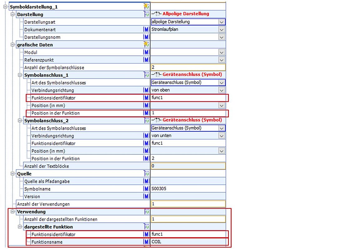
Figure 38: Symbol representation block with the “function identifier” and “position in function” properties, as well as the “function name” property within the usage block
In order to achieve this flexibility, a cardinal “usage” block is located in the symbol representation (36) section. The number of different uses is determined by the number of functions for which this symbol representation is used.
The cardinal “displayed function” block is located under the “usage” block in the hierarchy. This block can be used to indicate which functions the symbol stands for. The name of the function will be recorded in the “function name” property.
For the purposes of illustration, we will describe the relationship between symbol representation and function using the example of a power contactor (3RT2015-1BB44-3MA0). The equipment has the following schematic structure:
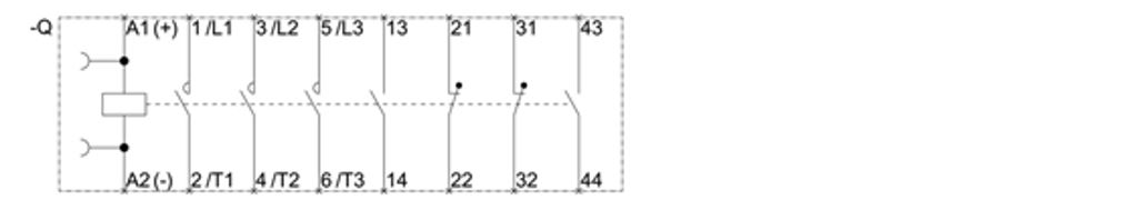
Figure 39: Circuit diagram of a power contactor (3RT2015-1BB44-3MA0)
The A1 and A2 connections are the control connections for the switching coil, the L1/T1, L2/T2 and L3/T3 connections form the three circuit breakers, and the 13/14, 21/22, 31/32 and 43/44 connections are the auxiliary contacts. The following frontal view of the unit (Figure 40) shows the designation of these four auxiliary contacts:
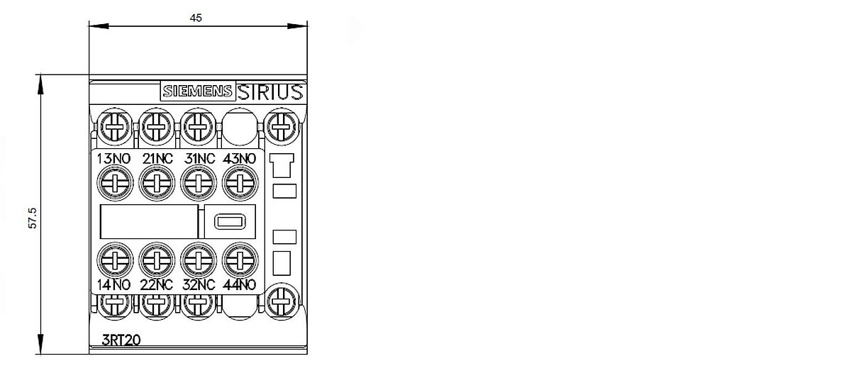
Figure 40: Frontal view 3RT2015-1BB44-3MA0
The example ECLASS description of the power contactor considered here contains the switching coil, the three combined circuit breakers, as well as one symbol representation each for the NO and NC (Figure 41). Other variants of the symbol and function descriptions are of course both conceivable and possible.
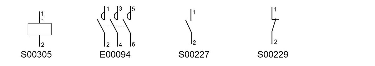
Figure 41: Individual symbols of a power contractor (examples from the standard symbol library)
The functional description (see section 3.2 Fixing Variants) of the power contactor contains eight functions (Figure 42) – one function for the coil, one function each for each of the three circuit breakers and four functions for the auxiliary contacts.
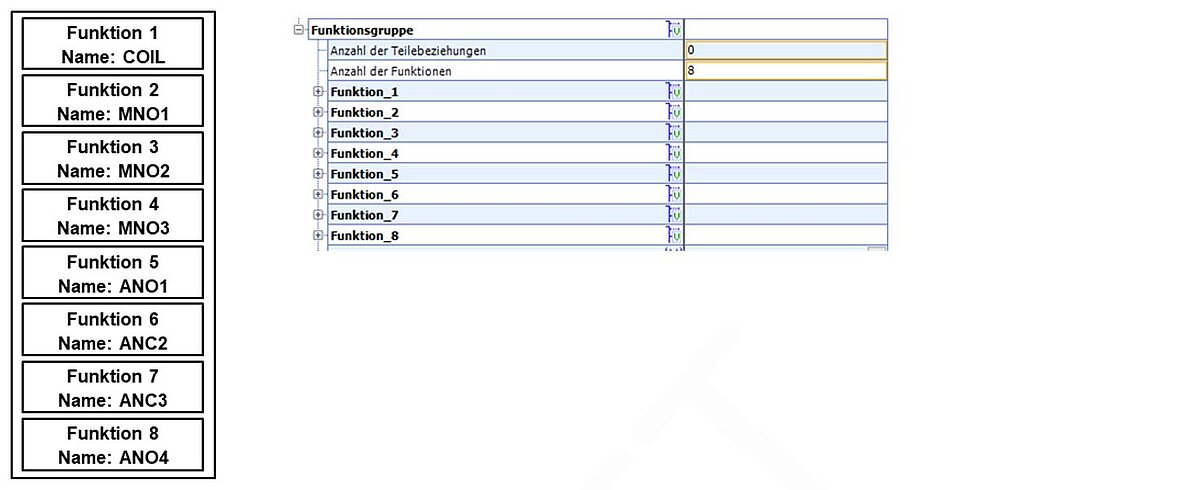
Figure 42: Power contactor functions
A look at the symbolic representation (Figure 43) of the three-phase circuit breaker shows that this symbol consists of six symbol connectors. Each symbol connector possesses the “function identifier” and “position in function” properties. A reference to the “displayed function” section in the “usage” block is produced through the “function identifier” property. In Figure 43 the association between the symbol connectors and the device connectors can be seen for the first circuit breaker. Furthermore, the 2 in the “usage” block shows that the symbol representation of the three circuit breakers is used once for the described functions, and that the symbol representation symbolizes three functions – that is, one function for each circuit breaker. The “function identifier” property has the value func3, and serves simply to produce a reference between “symbol connector” and “displayed function” when used (the other function identifiers, func3 and func4, are used for the other displayed functions, and thus the two other circuit breakers).
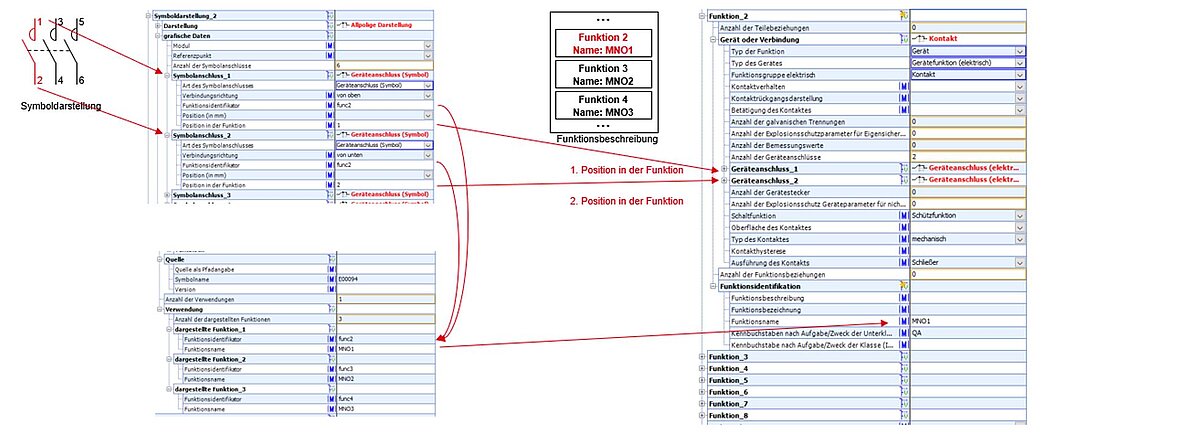
Figure 43: Relationship between symbol representation and function, using the example of a three-phase circuit breaker
By once again using the example of the power contactor as a reference, the symbol representation for an auxiliary switch can also be explained in more detail. The two auxiliary switches involve two NO contacts, which are described using a single symbol representation. The symbol representation employed for the NO contacts is used twice, and thus represents exactly one function. Within the description of the item, it is used for two functions (ANO1 and ANO4). The reference from the symbol representation to the ANO1 function is marked in red in Figure 60, while that to the ANO4 function is marked in blue. Here too, the “function identifier” property with the value func5 is used only to provide a reference between the symbol connectors and the displayed function in the usage section.
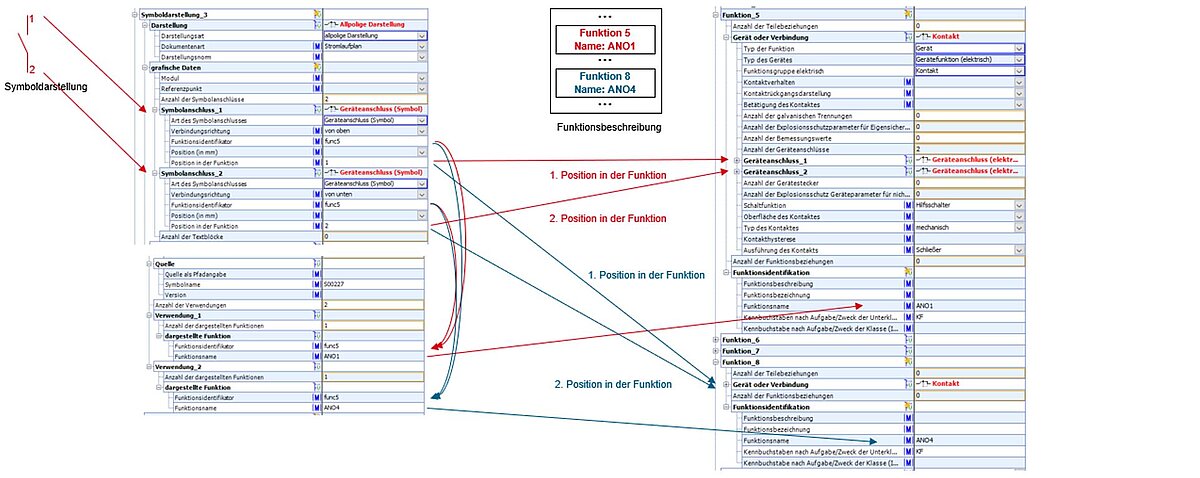
Figure 44: Relationship between symbol representation and function, using the example of an auxiliary switch
In order to show the flexibility of the modelling options in ECLASS, an additional variant will be described here. The symbol for the three-phase circuit breaker shown in Figure 59 will now be replaced by a single-phase circuit breaker. This symbol representation of an individual circuit breaker represents exactly one function, and is employed in the overall article description for three separate instances of use. The relationship between symbol representation and function description can be seen once again in Figure 45.
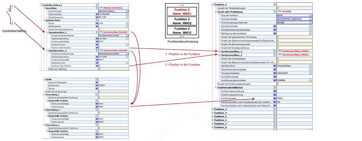
Figure 45: Relationship between symbol representation and function, using the example of a single-phase circuit breaker
If a device plug needs to be described using the symbol representation section, this takes place in a similar way, through a link to the functional description. When creating the link to the device plug connector (plug pins) in the functional description section, both the “position in function” and the “position in device plug” properties are necessary.
Source
Indicates where the file with the graphic symbol can be found.
| Level | Type | Structure element name | Application, explanation | Function for CAx and process |
|---|---|---|---|---|
1 | B | Source | Block indicating the source of the graphical symbol | Block used to describe the source |
2 | M | Source (source as path info) | Property for entering a link at which the graphic file can be found. | The link should be relative to the position of the BMECat file. Provides access to the graphic file for processing. Allowed formats are DXF and SVG |
2 | M | Symbol name | Designation of the graphical symbol | The symbol name should be unique, and should suggest the symbol and its use. |
2 | M | Version | Indication of the symbol version | Enables management of revisions. With this information, the CAE tool can determine whether the symbol has already been created in this or a more recent version. |
Representation
This block is used to indicate which documents the symbol is intended for. A CAE tool can use this information to assign the correct use to the symbol.
| Level | Type | Structure element name | Application, explanation | Function for CAx and process |
|---|---|---|---|---|
1 | B | Representation | Representation block | Block for the description of symbol representations |
2 | M | Document kind | Indicates what kind of document the symbol is suitable for. Basis is IEC 61082-1 (2006). |
|
3 | W | Flowchart | Flowchart | Flowcharts depict processes from different areas and thus enable a quick overview even of more complex issues. |
3 | W | Arrangement drawing | Arrangement plan (location) Arrangement plan (building) Arrangement plan (facility) | Drawing that provides an overview of an object in terms of arrangement, reference sizes and dimensions. |
3 | W | Connection table | Connection table | No definition, terminal diagram, terminal connection diagram? |
3 | W | Function diagram | Functional circuit diagram Logic function circuit diagram | No definition, abstract representation of an object with its functions |
3 | W | Circuit diagram | Circuit diagram | A circuit diagram, also called schematic or wiring diagram, is a graphical representation of an electrical circuit used in electrical engineering and electrical installation technology, usually at the level of individual modules or elements used in the field of electrical installation technology, such as switches, fuses, contactors, etc.. It does not take into account the real shape and arrangement of the components, but is an abstracted representation of the electrical functions and the current courses. |
3 | W | Connection diagram |
| Connection points shown in the circuit diagram and the lines and/or cables used, can be identified with corresponding reference identifiers. |
3 | W | Time sequence chart |
| Presentation of information about operational or functional processes in relation to time. |
3 | W | Overview diagram |
| Overview plan showing the representation and arrangement of the operating equipment in the room. |
2 | M | Representation standard | Indication of the representation standard being applied |
|
3 | W | ANSI / NFPA | Identification of the standard |
|
3 | W | IEC / DIN | Identification of the standard |
|
3 | W | ISO 1219 | Identification of the standard |
|
3 | W | JIC | Identification of the standard |
|
2 | P | Representation type | Specifies the connection diagram for which the symbol is needed. The property is polymorphous, and may be associated with additional properties, depending on its value. | . |
3 | W | All-pole representation |
| |
3 | W | Single-line representation |
| |
3 | W | Layout |
|
Polymorphous “all-pole representation” block
This value does not have additional specific properties.
Polymorphous “single-line representation” block
This value does not have additional specific properties.
Polymorphous “layout” block
This value supplies the following additional specific properties.
| Level | Type | Structure element name | Application, explanation | Function for CAx and process |
|---|---|---|---|---|
3 | M | Scale | Indication of scale in the form of a number (1:value) Example: a value of 50 indicates a scale of 1:50 | Needed by the CAx system to produce the correct conversion and representation |
3 | M | Layout view | The different possible views can be described here, if these are relevant for purposes of documentation. | The different views can be labelled here. |
4 | W | View from the front | Front view |
|
4 | W | View from the left | Side view left |
|
4 | W | View from the right | Side view right |
|
4 | W | View from above | Top view |
|
4 | W | View from below | Underside view |
|
4 | W | View from the rear | Back view |
|
4 | W | Mounting floor view | Describes attachment guidelines for mounting on a floor from the point of view of the part to be mounted. Example: Switching cabinet base on the floor. | The contours, mounting distances and mounting holes may be standard. Drilling hole information |
Graphical data
This block describes the relation between logical symbol elements and the product's functional structure.
| Level | Type | Structure element name | Application, explanation | Function for CAx and process |
|---|---|---|---|---|
1 | B | Graphical data | Graphical data block | Block for the description of graphical data |
2 | M | Module | Indication of the module size in mm When generating symbols, module size is the smallest grid unit of measurement between the graphical elements | Serves as the basis for CAx-system graphic representation options. Examples: 4mm, 1mm, 2.5mm, 5mm. |
2 | M | Reference point | Serves to position the insertion point, and acts as reference point for describing the position of the graphical elements (symbol connectors and symbol text). | Enables the graphical elements to be correctly arranged by the CAx system. Important note! All symbol-connector and text-block coordinate are provided relative to this point! |
2/3 | C | Number of symbol connectors | Call to symbol connectors block. See Symbol connectors | Calls the block that describes symbol connectors; number of calls is determined by number given here |
2/3 | C | Number of text blocks | Call to “text block” block See Text block | Calls the block that describes text blocks; number of calls is determined by number given here |
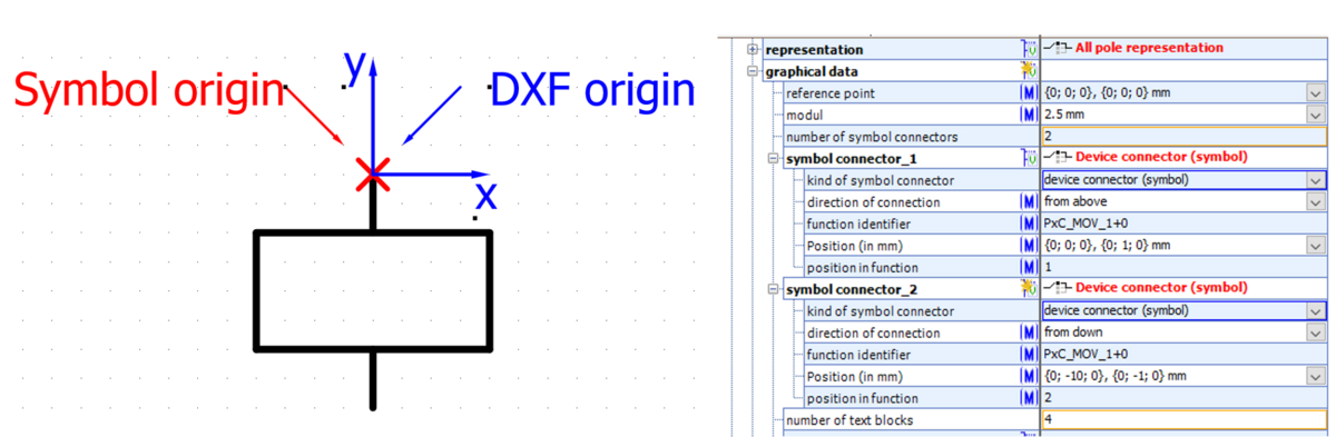
Point of origin
The point of origin is the point where all data in the graphical data block refer to.
In ECAD tools origin is typically the insert point which is shown on cursor top.
Note: Usually the point of origin is located at the first symbol connector (x=0; y=0).
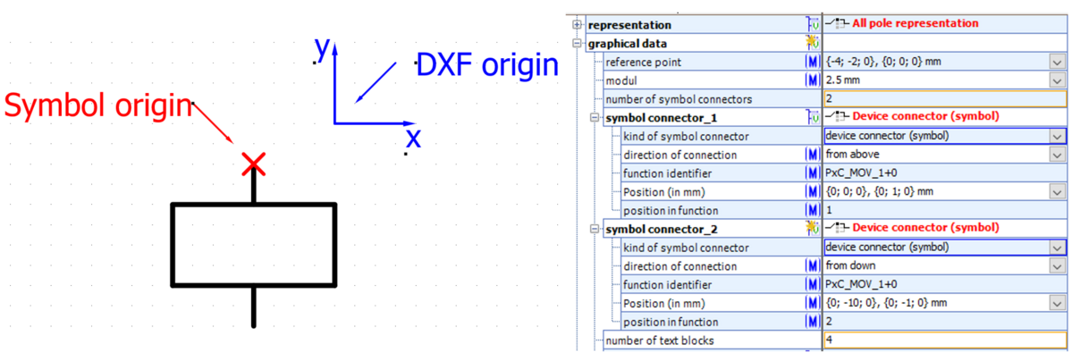
Reference point
The reference point describes the difference between graphic symbol in graphic file coordinate system and point of origin.
The value is the coordinate in graphic file (DXF drawing) where point of origin of symbol is located (usually first connector).
Note: if origin in graphic changes, only reference point needs to be changes. All other coordinates (e.g. connectors, text blocks) stay.
Example 1: Reference point and the point of origin are identical (values: x=0, y=0)
Example 2: Reference point and the point of origin are different (values here: x=-4, y=-2)
Symbol connectors
This block defines the position and additional characteristics of the graphical symbol connectors.
| Level | Type | Structure element name | Application, significance | Function for CAx and process |
|---|---|---|---|---|
1 | B | Symbol connectors | Symbol connector block | Block for the description of symbol connectors |
2 | M | Position (in mm) | Indicates the position of the connector in the symbol |
|
2 | M | Direction of connection | Indicates the direction from which the wiring line meets the graphical symbol connector | The values contained in the list refer to to the mechanism’s point of view. Some values are thus not meaningful here. |
3 | W | From above |
|
|
3 | W | From down |
|
|
3 | W | From left |
|
|
3 | W | From right |
|
|
3 | W | In front |
| This value has NO MEANING in a 2D symbol |
3 | W | From behind |
| This value has NO MEANING in a 2D symbol! |
2/3 | P | Kind of symbol connector | Specifies which connection or connections the symbol connector represents. Associated with additional specific properties depending on the value. | Assists the CAx system in assigning the connection to the correct function. |
3 | W | Device connector (symbol) | The symbol connector represents a device connector in a function. For specific properties, see Polymorphous “device connector (symbol)” block |
|
3 | W | Device plug (symbol) | The symbol connector represents a device plug in a function. For specific properties, see Polymorphous “device plug (symbol)” block
|
|
3 | W | Device plug connector (symbol) | The symbol connector represents a plug pin in a device plug in a function. For specific properties, see Polymorphous “device plug connector (symbol)” block |
|
3 | W | Virtual connector (symbol) | The symbol connector represents a group of device connections, plugs and/or pins in one or more functions. For specific properties, see Polymorphous “virtual connector (symbol)” block |
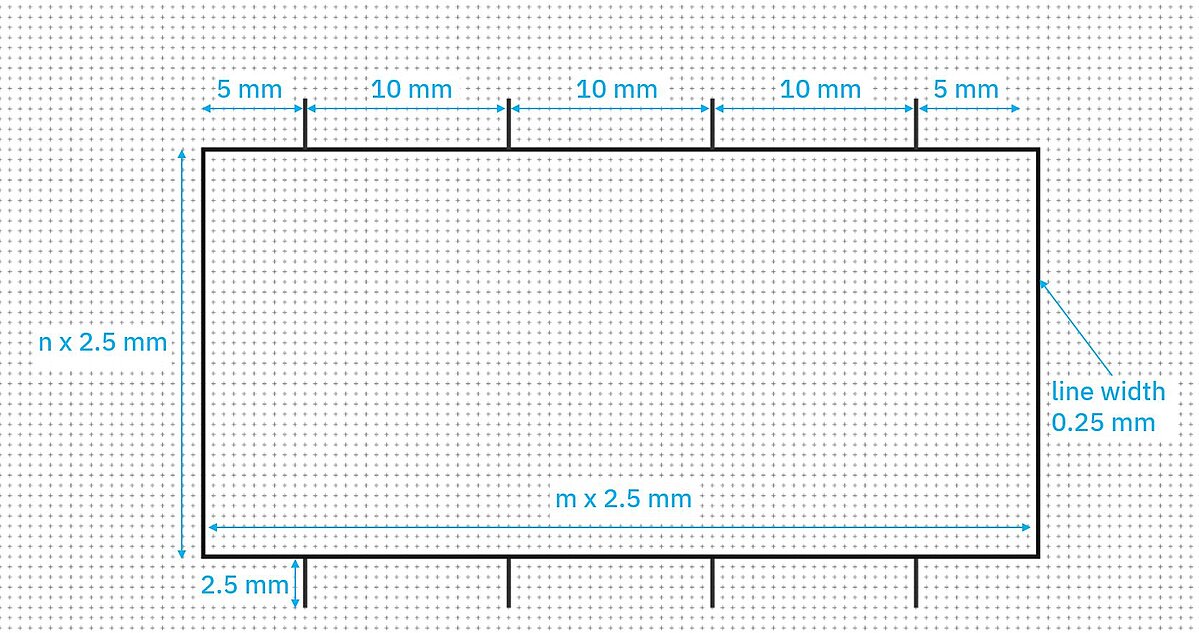
Display of circuit diagram symbols
The module [M]. The unit M is used as a module to harmonize the graphical representation of objects, e.g. display grids, field divisions, drawing grids and symbol sizes. Determination of module dimension [mm] to 2.5 mm (DIN EN 61082-1 chapter 5.7.3.2)
This results in the following distances for connections when creating symbols:
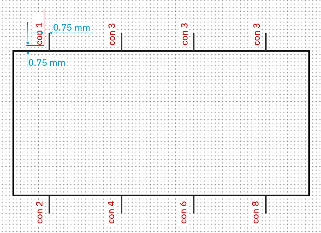
The spacing of the connections must be at least 2 x module dimension (i.e. 5 mm) in order to provide sufficient space for the labeling. A minimum distance of 4x module dimension between the connections is recommended.
The first connection from the left is placed 5 mm from the outer edge. DIN EN ISO 81714-1 chapter 6.11.
The distance from the "box" (contour of the graphic symbol), i.e. the connection line, to the positioning of the connection should also be 2.5 mm (this refers to the way the connections are led out so that they are not placed directly on the frame) DIN IN ISO 81714-1 Chapter 6.12.
Example: symbol with eight connections and dimensions
Polymorphous “device connector (symbol)” block
The symbol connector represents a device connector in a function.
| Level | Type | Structure element name | Application, significance | Function for CAx and process |
|---|---|---|---|---|
4 | M | Function identifier | Specifies an identifier employed in the “usage” block to refer to the function(s) in which the referenced connection is located. |
|
4 | M | Position in function | Numerical value that specifies which connection is indicated (independently of the name). Example: value=2 indicates the second connection in the function |
|
Polymorphous “device plug (symbol)” block
The symbol connector represents a device plug in a function.
| Level | Type | Structure element name | Application, significance | Function for CAx and process |
|---|---|---|---|---|
4 | M | Function identifier | Specifies an identifier employed in the “usage” block to refer to the function(s) in which the referenced connection is located. |
|
4 | M | Position in function | Numerical value that specifies which plug is indicated (independently of the name). Example: value=2 indicates the second plug in the function |
|
Polymorphous “device plug connector (symbol)” block
The symbol connector represents a plug pin in a device plug in a function.
| Level | Type | Structure element name | Application, significance | Function for CAx and process |
|---|---|---|---|---|
4 | M | Function identifier | Specifies an identifier employed in the “usage” block to refer to the function(s) in which the referenced connection is located. |
|
4 | M | Position in Function | Numerical value that specifies which plug is indicated (independently of the name). Example: value=2 indicates the second plug in the function |
|
4 | M | Position in device plug | Numerical value that specifies which plug pin inside the plug is indicated (independently of the name). Example: value=3 indicates the third plug pin in the plug. |
|
Polymorphous “virtual connector (symbol)” block
The symbol connector represents a group of device connections, plugs and/or pins in one or more functions. An example here would be a single-line representation that encompasses multiple connections.
| Level | Type | Structure element name | Application, significance | Function for CAx and process |
|---|---|---|---|---|
4 | M | Connector name |
|
|
4 | M | Connector designation |
|
|
4 | M | Connector description |
|
|
4 | M | Type of virtual connector |
|
|
4/5 | C | Number of assigned connectors |
|
|
5 | B | Assigned connector |
|
|
5 | P | Type of assigned connector | Query regarding type of assigned connector (polymorphous) | Selection of the kind of symbol connector Assists the CAx system in determining the correct symbols for the intended representation type |
6 | W | Device connector (assigned connector) | Identification of the polymorphous device connector block |
|
7 | M | Function identifier |
|
|
7 | M | Position in function |
|
|
6 | W | Device plug (assigned connector) | Identification of the polymorphous device plug block |
|
7 | M | Function identifier |
|
|
7 | M | Position in function |
|
|
6 | W | Device plug connector (assigned connector) | Identification of the polymorphous device plug connector block |
|
7 | M | Function identifier |
|
|
7 | M | Position in device plug |
|
|
7 | M | Position in function |
|
|
Text block
This block defines the position and additional characteristics of textual descriptions in the symbol representation.
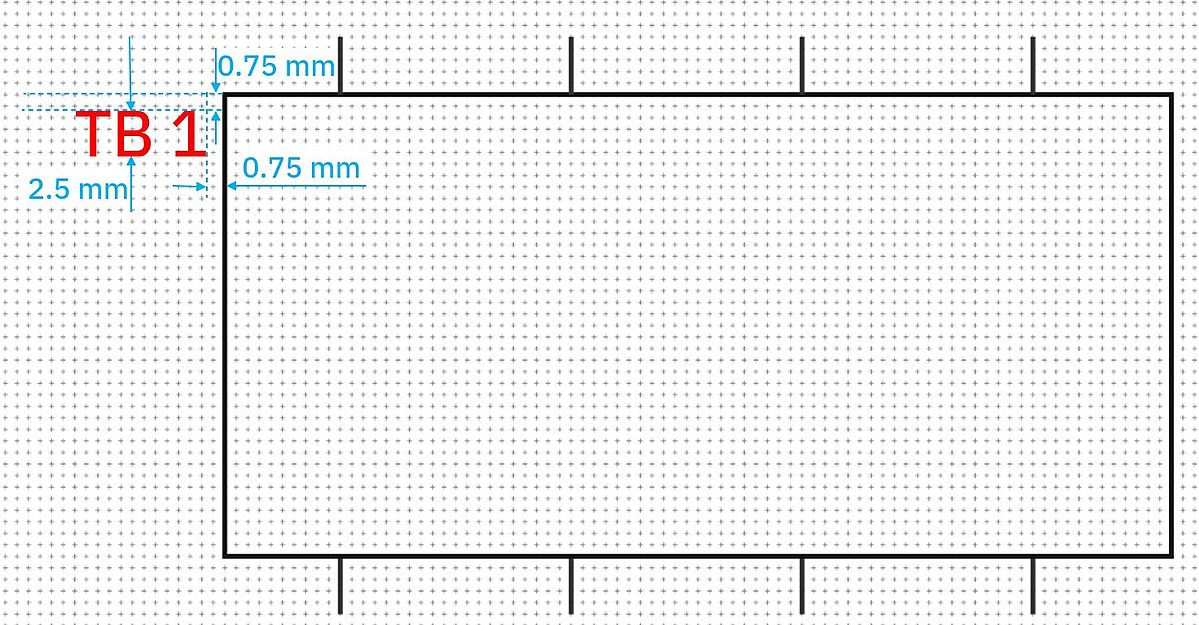
Recommendation of general distances and dimensions when creating symbols:
- Uniform labeling designation reference mark (formerly BMK or BMKZ) and additional information (according to DIN EN ISO 81714-2:2007, chapter 6.14)
- The reference mark is positioned to the left of the box at a distance of 0.75 mm
- The font height is 2.5 mm (DIN EN 61082-1 chapter 5.11)
- The spacing of the identification and description blocks can be found in the standard DIN EN ISO 81714-2
- The typeface (text font) must be designed in accordance with DIN EN ISO 81714-2:2007, chapter 6.7.3.
- Texts in the "box" (outline of the graphic symbol) itself should also have a distance from the "box" (outline of the graphic symbol) of 0.75 mm (but at least 2x line width)
Example: text designation reference mark
- Positioning "Connection marking" according to DIN EN ISO 81714-2 chapter 6.8.4.
- 0.75 mm from the "box" (contour of the graphic symbol)
- 0.75 mm from the connection
- Text alignment connection name
- The text in a document must be aligned horizontally or vertically and be legible when the document is viewed from the bottom or from the right (DIN EN 61082-1 chapters 5.2 and 5.12.3). We hereby specify the legibility of the "connection name" from the right.
Example: text connection position
| Level | Type | Structure element name | Application, significance | Function for CAx and process |
|---|---|---|---|---|
1 | B | Text block | “Text block” block | Block for the description of text blocks |
2 | M | Diagram level | Specifies which layer contains the information in the symbol file | Needed by the CAx system to find the information and create the correct representation. |
2 | M | Functional text block | Indicates that the text block is specialized for a CAx-specific use of data. | List of options: descriptive block, horizontal cross-reference block, identifying and descriptive block, identifying block, vertical cross-reference block
|
2 | M | Max. representation height | Max. vertical extension in mm | Needed for the representation of the text block. |
2 | M | Max. representation with | Max. horizontal extension in mm | Needed for the representation of the text block. |
2 | M | Position | Indication of the coordinate point of the text block on the graphical symbol, relative to the graphical symbol’s reference point. | Needed by the CAx system to place the text block |
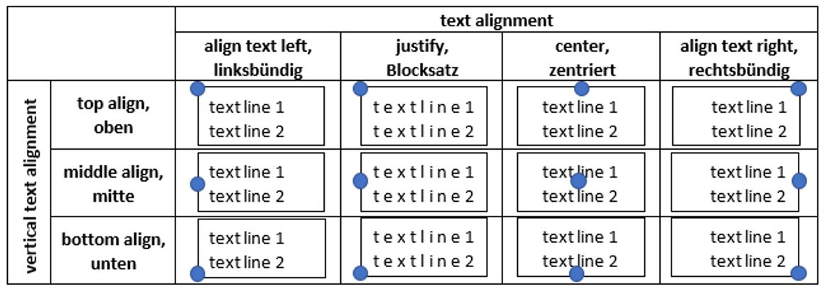
2 | M | Text alignment | Expansion of text in reading direction | List of options: left justified, right justified, centered, full justification |
2 | M | Text name | Text designation |
|
2 | M | Text rotation angle | Indication of the number of degrees by which the text is rotated from the horizontal, in a counterclockwise direction. | Needed by the CAx system to create the representation. |
2 | M | Vertical text alignment | Expansion of text perpendicular to reading direction | Needed by the CAx system to create the representation. List of options: bottom, middle, top |
2/3 | C | Number of text lines | Call to the text line block | Calls the block that describes text lines; number of calls is determined by number given here |
3 | B | Text lines | Text line block | Block for the description of text lines |
3/4 | C | Number of text strings | Call to the text string block | Calls the text string description block; number of calls is determined by number given here |
4 | B | Text strings | Text string block | Interpretation of the text string to CAx-relevant data |
4 | P | Text type | Query regarding text type (polymorphous) | Selection of text type |
5 | W | Device connector – value of property | Identification of the polymorphous device connector – value of property block |
|
6 | M | Function identifier | Unique designation of the function in the symbol |
|
6 | M | Position in function |
| Number representing sequential position in function |
6 | M | Property identifier | Unique identifier for the property |
|
6 | M | Property preferred name | Designation of the property |
|
5 | W | Device plug connector – value of property | Identification of the polymorphous device plug connector – value of property block |
|
6 | M | Function identifier | Unique designation of the function in the symbol |
|
6 | M | Position in device plug | Assigned number in the plug |
|
6 | M | Position in function |
|
|
6 | M | Property identifier | Unique identifier for the property |
|
6 | M | Property preferred name | Designation of the property |
|
5 | W | Device plug – value of property | Identification of the polymorphous device plug – value of property block |
|
6 | M | Function identifier | Unique designation of the function in the symbol |
|
6 | M | Position in function |
|
|
6 | M | Property identifier | Unique identifier for the property |
|
6 | M | Merkmalsbenennung | Property preferred name | Designation of the property |
5 | W | Fixed text | Identification of the polymorphous block |
|
6 | M | Fixed text content | Indication of the fixed text to be used |
|
5 | W | Name of property | Identification of the polymorphous block | Displays the name of a property |
6 | M | Function identifier | Description as above | Reference to the applicable function through use of the function identifier |
6 | M | Property identifier | Description as above | Reference to the property within the function on the basis of the ECLASS identifier |
6 | M | Property preferred name | Description as above | Additional description of the property name for the purposes of better user readability |
5 | W | Unit of property | Identification of the polymorphous block |
|
6 | M | Function identifier |
| description as above |
6 | M | Property identifier |
| Description as above |
6 | M | Property preferred name |
| Description as above |
5 | W | Value of property | Identification of the polymorphous block |
|
6 | M | Function identifier |
| Description as above |
6 | M | Property identifier |
| Description as above |
'6 | M | Property preferred name |
| Description as above |
5 | W | Virtual connector – value of property | Identification of the polymorphous block |
|
6 | M | Connector name |
| Description as above |
6 | M | Property identifier |
| Description as above |
6 | M | Property preferred name |
| Description as above |
5 | W | Functional text string | Identification of the polymorphous block |
|
| ||||
6 | P | Type of functional text string | Query regarding type of functional text string (polymorphous) | Selection of text-string type: Cross-reference or reference designation |
7 | W | Cross-reference | Identification of the polymorphous block |
|
8 | M | Function identifier | Description as above | Description as above |
7 | W | Reference designation | Identification of the polymorphous block |
|
Overview of all combinations of text block orientations (blue dot shows insert position):
Usage
This block is used to describe which functions are represented by the symbol. Example: Symbol for a power contact represents contact functions 1 to 3.
| Level | Type | Structure element name | Application, significance | Function for CAx and process |
|---|---|---|---|---|
1 | B | Usage | Usage Block | Block for usage description |
2 | C | Number of displayed functions | Call to function block | Calls the block that describes displayed functions; number of calls determined by number given here |
2/3 | B | Displayed function | Displayed function block | Block for description of displayed functions |
4 | M | Function identifier | Description as above |
|
4 | M | Function name | Designation of function | See 4.2 Function |