2. Mechanical and electrical construction
This block serves as the basis for all physical descriptions of devices relevant for construction, as well as the various indications of positions and directions associated with them. Figure 5 shows the structure of the block.

Figure 5: Overview of block
For each device, part described in this block, a standard mounting plane in the preferred mounting position is defined for the purpose of common arrangement and assembly.
2.1 General rules for dimensions and directions
The standard mounting plane is placed on the X/Y plane, where the X-direction is the direction of the arrangement in rows (see Figure 6). Thus, the X-direction is to the right (horizontal), the Y-direction is toward the top (vertical), and the Z-direction is on the axis approaching the X/Y level as viewed perpendicularly from above (a right rotating cartesian coordinate system).
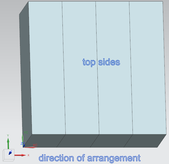
Figure 6: Orientation of 3D models in coordinate system
CAD systems which use different orientations needs to transform all mechanical information and 3D file on their own during import.
2.2 Origin and dimensions
Block “Size dimension” defines the enveloping body include related origin and dimensions in mounted state. CAD needs dimensions in installed mounted state to
- place next device on correct position automatically
- create 2D cabinet design symbols (e.g. rectangle, circle) on the fly if missing
- create 3D model (e.g. cuboid, cylinder) on the fly if missing
Dimensions in mounted case do not include extensions which extend into close-by devices. Figure 7 shows an example.
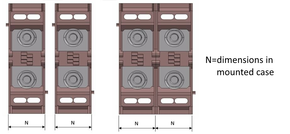
Figure 7: Example for dimensions in mounted case
For products which are combined in one device (e.g. push button with contact block) or for products which are mounted on other product as own device (e.g. overload relay on contactor), it’s not required to exclude extensions in dimensioning. These products will be mounted with one fixing point on component receptacle of other product and not side by side without relation to each other.
To define dimensions without extensions could be helpful to avoid collisions between on the fly created 3D models.
ECLASS defines 2 different enveloping body types include related properties (see Figure 8). All positions used in aspects are related to the origin defined in enveloping body type.
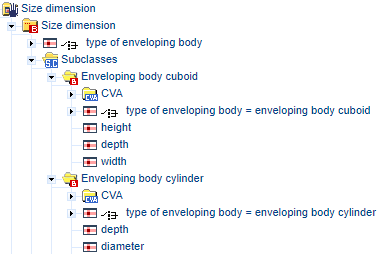
Figure 8: Enveloping body types include properties
Cuboid enveloping body
With a cuboid type enveloping body, the origin is the outermost, left, lower hindmost point of the enveloping body. All positions therefore have values greater than or equal to zero in all directions.
Dimensions and their directions:
- width (BAF016) – size in x-direction
- height (BAA020) – size in y-direction
- depth (BAB577) – size in z-direction
Figure 9 shows a cuboid body with origin in outermost, left, lower hindmost corner.
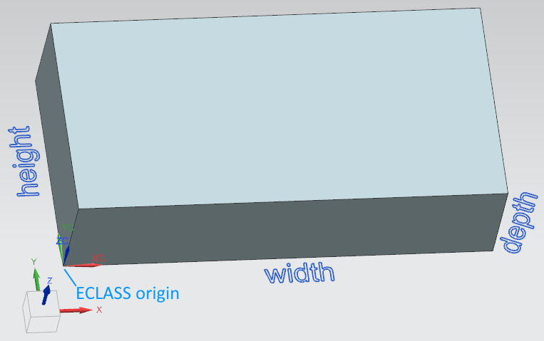
Figure 9: Cuboid in the coordinate system
Cylindrical enveloping body
For an enveloping body of the cylindrical type, origin the middle, rearmost point of the enveloping body. Thus, the references for the X- and Y-directions are on the axis of symmetry and can take either positive or negative values. As with cuboid enveloping bodies, positions on the Z axis will typically contain only values greater than or equal to zero.
Dimensions and their directions:
- diameter (AAC895) – size in x/y-face
- depth (BAB577) – size in z-direction
Figure 10 shows a cylinder body with origin in center of bottom face.
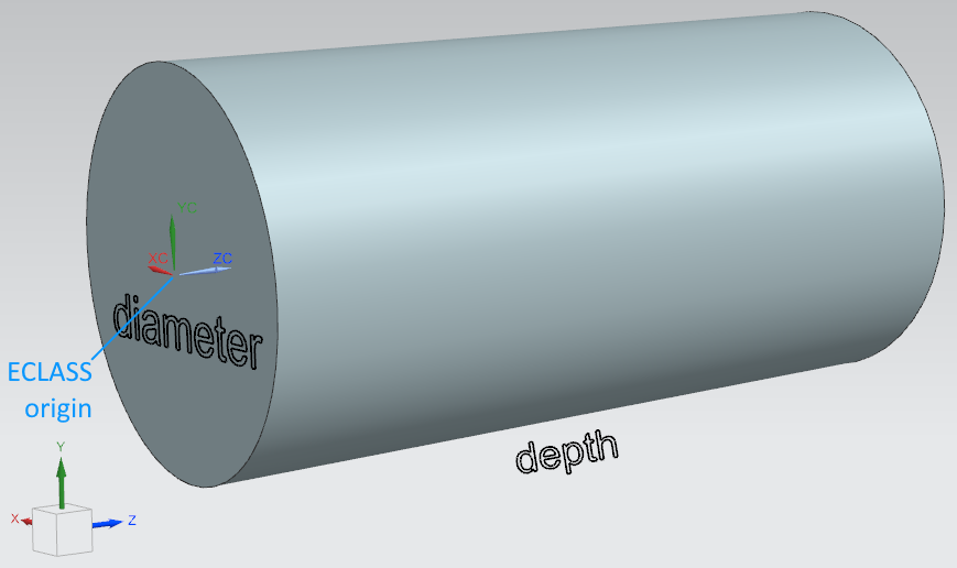
Figure 10: Cylindrer in the coordinate system
Orientation and origin in 3D file
As enveloping body and related origin gives opportunity to create 3D model on the fly by CAD tool, related 3D file needs to respect these definitions. Otherwise, all positions (e.g. connectors) are not consistent between 3D model in file and on the fly created ones.
These are the main rules:
- Orientation
The 3D model must be oriented as in chapter 2.1 General rules for dimensions and directions defined (model orientation = ECLASS orientation). - Origin
The origin of the 3D coordinate system must be on the position of the origin of the model based on dimensions in mounted case (model origin = ECLASS origin).
Figure 11 shows an example where extensions are part of 3D model in file
On the fly created 3D model | Related ECLASS origin | Origin in 3D model |
| | |
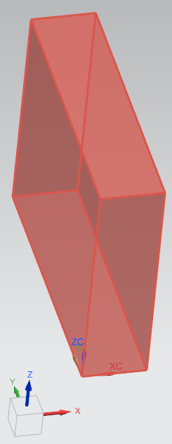
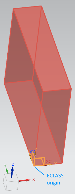
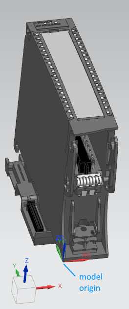
Figure 11: Coordinate system in 3D file
2.3 Other construction properties
Net weight (AAF040)
Weight of the product in mounted case without any additional products.
Mounting design (DE: Einbauform, AAN48)
Information on devices for standardized installation methods is specified here. The installation methods describe configuration-relevant assembly layouts and operating accessibilities.
The values are included in the value list of the characteristic:
ID, Value (EN,DE) | Meaning | Graphic |
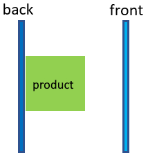
BAA194 surface mounting, Aufbau | Mounting surface is not penetrated, product fastening on assembly planes (e.g. wall, mounting plate, DIN rail, etc.) Examples: circuit breakers, contactors, relays, terminal blocks |
|
BAA877, serial installation, Reiheneinbau | Rail-mounted, dimensions in accordance with DIN 43880 Examples: modular installation devices like miniature circuit breakers, impulse switches |
|
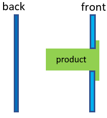
BAA496, front installation, Fronteinbau | Front is penetrated Examples: measuring devices, signaling lights, push buttons |
|
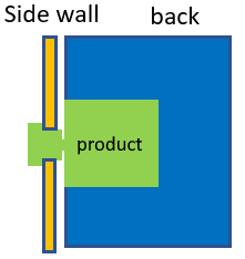
AAR681, side panel installation, Seitenwandeinbau | Side wall is penetrated by the actuator, product fastening on assembly planes (e.g. mounting plate, DIN rail, etc.) Examples: main switches, load switches |
|
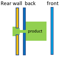
AAR682, back plane installation, Rückwandeinbau | Rear wall and assembly plane are penetrated, fastening on assembly planes (e.g. mounting plate, DIN rail, etc.) Examples: frequency converter with water cooling from back, main switches with actuation on back side |
|
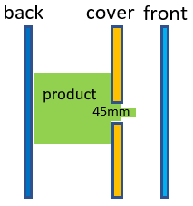
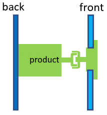
BAB459, intermediate building, Zwischenbau | Combination of surface installation and front installation and releasable coupling between both Example: circuit breaker with actuation in door |
|
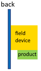
AAV213, Field devices attachment, Feldgeräte Anbau | Decentral installed on assembly planes in the process environment, product fastening on the field device. Systemic mounting method Examples: probes, decoders, tachometers | |
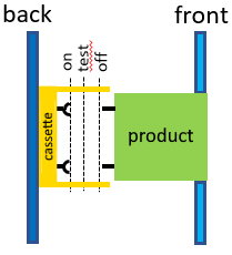
ABC172, withdrawable unit, Einschub | Inserted into a cassette with a handle according to IEC 61439-1. Example: air circuit breaker |
|
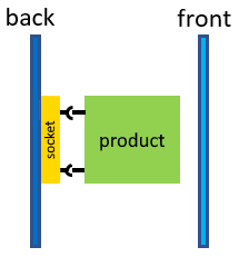
ABC173, plug insert, Steckeinsatz | Plugged onto a socket. Example: relay module in base terminal |
|
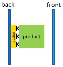
ABZ684, busbar installation, Sammelschienen-aufbau | Placed and fastened on a busbar, product fastening on the busbar assembly plane. Examples: busbar mounting fuse elements, fuse switch disconnect bars |
|
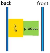
ABZ685, component mounting, Komponenten-anbau | Mounted on/at/in other product Examples: Auxilliary block on contactor, Contact block on push button |
|
2.4 Housing descriptions
This cardinal block could be used to describe all parts of the housing of a device. This block is typical not relevant for CAD systems.
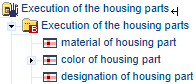
Figure 12: Housing part
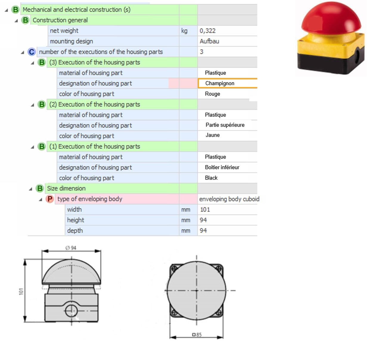
Figure 13: Example of a mushroom head push button