4.1 Connection
Chapter navigation
Connection
The term connection is used for various meanings.
1. For a real connection of a line, for different media e.g. water, gas, electricity, at a connection point.
2. For the logical, symbolic connection of lines to drawing symbols in documentation.
This area is used for the general description of real connections.
A connection identifier is assigned to uniquely identify a real connection.
Each real connection must be described individually.
Recommendation for creation the connection identifier:
Unless you have an identifier specification from your design systems, the best way to number the connections of the equipment is as follows:
From top left to bottom left from left to right, from back to front (function related). Very often it happens in electrical engineering that several real connections are combined to one logical connection see examples:
Example circuit breaker logical 1 Connection 2 real connections Line and phase bridge connection with 1 actuation.
| Power contactor logical 1 connection 2 real line connections with 1 actuation.
|
Figure 46: CAx connection example real connection | Figure 47: CAx connection example real connection |
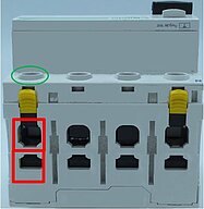
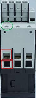
Figure 48: CAx connection example real connection
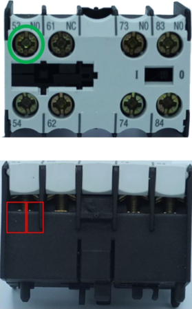
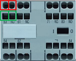
Auxiliary switch block: Screw connection Logical 1 connection 2 real connections with 1 actuation | Connection: Spring-cage connection Logical 1 connection 2 real connections with 2 actuations |
|
|
In the Functions section, the logical connections are then described according to their use in the CAE documentation and referenced to the connections described here in this block via the connection identifier.
Features real connection
Level | Species | Structure item Name | Application, meaning | Function for CAx and process |
|---|---|---|---|---|
1 | C | number of connections | Specification of the number of existing real connections | Calls the block to describe a real connection according to the number |
1/2 | B | Connection | Block | |
3 | M | Connection identifier | Clear designation of a connection point (connection) | For further information see: 4.1 Connection |
3 | M | Connection direction | Specifies the direction from which the wiring meets the terminal in standard installation use | Values: from behind from below from above from front from left from right |
3 | M | Position (in mm) | Specification of the physical position of the connection | For further information see: 4.1 Connection#Explanation of the position of the connection |
3 | M | Connection removable | Indication whether the connection can be removed without disconnecting the wiring. | Important for the specification of the connection symbol |
3 | M | Connection group | Alphanumeric designation, if several connections are to be managed mechanically or electrically together. Example mechanical: multipole connector or a terminal strip, electrical: infeed, outgoing feeder, assignments of systemic connection adapters or connection group assignments, e.g. overcurrent relay. Example: "X1 | Helps the system/designer to assign and arrange the connections. |
3 | C | Number of part relationships | See chapter 3.1 Parts Relations | |
3 | P | Type of connection | Call Type of connection polymorphic | Connection type-specific call of description blocks |
4 | W | Connection plug | Identification of the polymorphic block | For the following block see 4.1 Connection#Connection plug
|
4 | W | Single electrical connection | Identification of the polymorphic block | For the following block see 4.1 Connection#Single electrical connection |
4 | W | Single hydraulic connection | Identification of the polymorphic block | Block not further specified |
4 | W | Single connection pneumatic | Identification of the polymorphic block | Block not further specified |
4 | W | Individual connection Process engineering | Identification of the polymorphic block | Block not further specified |
Connection plug
Level | Species | Structure item Name | Application, meaning | Function for CAx and process |
|---|---|---|---|---|
1 | B | Connection plug | Block |
|
2 | M | Design of the connector | Describes the type of connector design to plug in | Is required for project planning and for assessing the connector. Values: female, male, mixed |
2 | M | Connector type | Specification of a standardized connector design | Is used to clarify the fit of the plug connection. |
2 | M | Connection position | Angle of rotation of the connector between its home position and the assembly position | Is used for the conversion of positions during the wiring routing of standard connectors |
2 | M | Description of the connection position | Possibility for additional textual information on the connection position | Instructions for use can be given here |
2/3 | C | Number of the plug connection | Cardinal call of the description blocks for the connection e.g. with possible | Calls up the block for the description of the mechanics of an electrical connection according to the number |
3 | B | Plug connection | Block for describing the electrical connection | Description of electrical characteristics for connection |
4 | M | Connection identifier | Clear designation of a connection point (connection) | Is required for wire prefabrication |
4 | M | Position of the plug connection (in mm) | Specification of the physical position of the plug connection | For further information see: 4.1 Connection#Explanation of the position of the connection |
4 | M | Design of the plug connection | Description of the plug connector design according to the delivery condition Values: plug socket, plug pin, plug pin or socket, optical plug contact, plug housing, plug contact tongue | Is used to clarify the fit of the plug connection. |
4 | M | Type of plug connection | For the description of physically different plug connections. Values: electrical, hydraulic, mechanical, optical, pneumatic, process engineering | Approach for the further description of mechatronic connectors. (To be expanded) |
4 | C | Number of parts relationships | Only if, depending on the plug connection, other additional parts are required than already defined on the article level under part relationship. See chapter 3.1 Parts Relations | Calls the block for the part relationship description according to the number. Additional systemic parts required for the connection can be described here |
Single electrical connection
Level | Species | Structure item Name | Application, meaning | Function for CAx and process |
|---|---|---|---|---|
1 | B | Single electrical connection | Block | Block and collection of characteristics for the description of individual electrical connections |
2 | B | Wiring | Block for describing the possible wiring | Enables a machine- readable wiring description |
3 | M | Material of the electrical connection | Describes the material of the surface of the connection | Is required for project planning and for the assessment of the contacting. |
3 | M | Bridge connection | A bridge connection can only be contacted via a special systemic electrical bridge, not via a wire. | Is used for detail clarification during wiring routing. |
3 | M | Colour of the electrical connection | Colour of the material enveloping the connection | Additional marking option for differentiation in the process |
3 | C | Number of versions of the electrical connection | Cardinal call of the description blocks for the connection e.g. with possible | Calls the block for the execution description of the mechanics of an electrical connection according to the number |
3/4 | B | Design of the electrical connection | Block for describing the electrical connection | Block for describing the electrical connection |
4 | M | Stripping length | Required length of stripping to ensure adequate contact | Is required for wire prefabrication |
4 | M | Permissible conductor types | Approved connectable conductor types with intended wire end treatment values: solid conductor stranded conductor fine-stranded conductor with splice protection fine-stranded conductor without splice protection Flat rail Flat belt phase busbar (new for 11.0) | Describes the types of conductors that can be used for wiring preparation |
4 | M | Off-drive size | Size and design of the operating tool for the connection | For use with automatic wiring to change the tool |
4 | M | Tightening torque | Specification of the required torque as min. / max. specification If there is only one value, it must be entered in both fields. | Is required for safe contact making and can also be logged by screwing machines |
4 | M | Actuation vector | Position and direction for operation with a tool | Is required for automatic screwing |
5 | B | Cross section of the conductor wire (mm²) | Block for describing the usable conductor in mm² | Is required for wiring logistics and wire prefabrication |
6 | M | Fine-wire conductor cross-section with splice protection (mm²) | Standard cross-sectional absorption capacity of the clamping point as min. / max. Specification for the conductor type with final treatment | Is required for wiring logistics and wire prefabrication |
6 | M | Fine-wire cross-section without splice protection (mm²) | Standard cross-sectional absorption capacity of the clamping point as min. /max. Specification for the conductor type without final treatment | Is required for wiring logistics and wire prefabrication. |
6 | M | Multi-wire conductor cross-section (mm²) | Standard cross-sectional absorption capacity of the clamping point as min. /max. Specification for the conductor type without final treatment | Is required for wiring logistics and wire prefabrication |
6 | M | Solid conductor cross-section (mm²) | Standard cross-sectional absorption capacity of the clamping point as min. /max. Specification for the conductor type without final treatment | Is required for wiring logistics and wire prefabrication |
6 | M | Total maximum of the cross-section (mm²) | Specification of the maximum possible cross-section in (mm²) | Is required for wiring logistics and wire prefabrication. |
6 | M | Number of fine-stranded conductors without splice protection | Number of clampable wires per real connection | Is required for wiring logistics and wire prefabrication. |
6 | M | Number of stranded conductors (mm²) | Number of clampable wires per real connection | Is required for wiring logistics and wire prefabrication |
6 | M | Number of solid conductors (mm²) | Number of clampable wires per real connection | Is required for wiring logistics and wire prefabrication |
6 | M | Number of fine-stranded conductors with splice protection (mm²) | Number of clampable wires per real connection | Is required for wiring logistics and wire prefabrication |
Note Block Cross-section of the conductor wire (mm2): describe not applicable number with 0 | ||||
5 | B | Cross section of the conductor wire (AWG/KCMIL) | Block for describing the usable conductor in AWG/KCMIL (American standard) | Is required for wiring logistics and wire prefabrication. |
6 | M | Total maximum of the cross-section | Specification of the maximum possible cross-section in AWG/KCMIL | Is required for wiring logistics and wire prefabrication |
6 | M | min. fine wire cross-section with splice protection (AWG/KCMIL) | Standard cross-sectional absorption capacity of the clamping point as minimum specification for the conductor type with final treatment | Is required for wiring logistics and wire prefabrication |
6 | M | max. fine wire cross-section with splice protection (AWG/KCMIL) | Standard cross-sectional absorption capacity of the clamping point as minimum specification for the conductor type with final treatment | Is required for wiring logistics and wire prefabrication |
6 | M | min. fine wire cross-section without splice protection (AWG/KCMIL) | Standard cross-sectional absorption capacity of the clamping point as minimum specification for the conductor type with final treatment | Is required for wiring logistics and wire prefabrication |
6 | M | min. stranded wire cross section(AWG/KCMIL) | Standard cross-sectional absorption capacity of the clamping point as minimum specification for the conductor type with final treatment | Is required for wiring logistics and wire prefabrication |
6 | M | max. stranded wire cross section(AWG/KCMIL) | Standard cross-sectional absorption capacity of the clamping point as minimum specification for the conductor type with final treatment | Is required for wiring logistics and wire prefabrication. |
6 | M | Number of solid conductors | Number of clampable wires per real connection | Is required for wiring logistics and wire prefabrication. |
6 | M | min. solid wire conductor cross section(AWG/KCMIL) | Standard cross-sectional absorption capacity of the clamping point as minimum specification for the conductor type with final treatment | Is required for wiring logistics and wire prefabrication. |
6 | M | max. solid conductor cross section(AWG/KCMIL) | Standard cross-sectional absorption capacity of the clamping point as minimum specification for the conductor type with final treatment | Is required for wiring logistics and wire prefabrication. |
6 | M | max. fine wire cross-section without splice protection (AWG/KCMIL) | Standard cross-sectional absorption capacity of the clamping point as minimum specification for the conductor type with final treatment | Is required for wiring logistics and wire prefabrication |
6 | M | Number of stranded wires Manager (AWG/KCMIL) | Number of clampable wires per real connection | Is required for wiring logistics and wire prefabrication |
6 | M | Number of fine wires conductor with splice protection (AWG/KCMIL)
| Number of clampable wires per real connection | Is required for wiring logistics and wire prefabrication |
6 | M | Number of fine wires conductor without splice protection (AWG/KCMIL) | Number of clampable wires per real connection | Is required for wiring logistics and wire prefabrication |
Note Block Cross section of the conductor wire (AWG/KCMIL): Describe not applicable number with 0 | ||||
5 | B | Flat conductor connection | Block for describing possible flat conductor connections | Is required for wiring logistics and wire prefabrication |
6 | M | Minimum cross section (mm2) | Information about the required minimum cross-section for the rated current | Is required for rail prefabrication. |
6 | B | Strip connection | Block for describing a strip connection | Is required for wiring logistics and strip prefabrication |
7 | M | Connection of the Strip | Textual application note on strip treatment | Can be used for technical specifications for strip prefabrication |
7 | M | Hole pattern | Specifying an identifier for the hole pattern Graphical indication of breakthroughs in the strip | Is required for strip preproduction |
7 | M | Number of stripes | Indication of how many stripes can be connected per connection | Is required for strip preproduction |
7 | M | Number of slats | Indicates how many slats the conductor has. | Is required for strip preproduction |
7 | M | Thickness of the slats (mm) | Specification of the thickness of a lamella in mm | Is required for strip preproduction |
7 | M | Width of the slats (mm) | Specification of the width of a slat in mm | Is required for strip preproduction |
6 | B | Bar connection | Block for describing a bar connection | Is required for wiring logistics and bar prefabrication |
7 | M | Hole pattern | Specifying an identifier for the hole pattern Graphical indication of openings in the bar | Is required for bar prefabrication |
7 | M | Material of the suitable bar
| Information about the material of the bar | Is required for procurement and bar prefabrication |
7 | M | Number of bars | Indication of how many bars can be connected per connection | Is required for procurement and bar prefabrication |
7 | M | Bar surface | Information about the surface treatment of the bar | Values: black painted, bright, tinned |
7 | M | Bar width (mm) | Specification of the width of a bar in mm | Is required for procurement and bar prefabrication |
7 | M | Bar thickness (mm) | Specification of the thickness of a bar in mm | Is required for procurement and bar prefabrication |
2 | C | Number of rated values of device functions | Number of rated values of device functions | Indicates how many rated value sets are available for the connection |
2/3 | B | Rated value for connection | Block Rated value for the connection. Possibility to specify rated values for the connection | Helps the system/designer to assign and arrange the connections |
4 | M | Rated insulation voltage | specifies the maximum value of the electrical voltage for the connection | Helps the system/designer to assign and arrange the connections |
4 | M | Rated uninterrupted current | is the current that the connection can carry in uninterrupted duty | Helps the system/designer to assign and arrange the connections |
4 | M | Rated voltage | specifies the maximum value of the electrical voltage of the connection in normal operation | Helps the system/designer to assign and arrange the connections |
4 | M | Rating according to | Possibility to specify a reference standard or test | Helps the system/designer to assign and arrange the connections |
Explanation of the position of the connection
The feature indicates the physical position (AXIS 1D Data Type) of the respective connection on the device and the direction from which the conductor is inserted.
The point is in the middle of the connector funnel opening and at the maximum rear point that the connector can reach. The point is specified in mm using the x/y/z-coordinates in relation to the reference point of the device. The alignment is described by an additional unit vector.
The Connection direction feature is intended for use in line routing. The connection direction indicates the preferred direction from which the conductor runs on the connection from the installation point of view. A standard preferred direction for normal use must be specified here.
- from behind
- from below
- from above
- from front
- from left
- from right
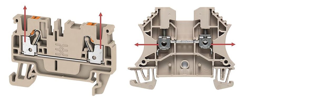
Figure 49: CAx connection example Connection direction
CAx connection example: Connection direction in XML
- <POINT>
° <POINT X="92.5" />
° <POINT Y="43.3" />
° <POINT Z="157.2" />
° </POINT>
- <DIRECTION>
° <DIRECTION X="0" />
° <DIRECTION Y="0" />
° <DIRECTION Z="-1" />
° </DIRECTION>
° </DIRECTION>
Electrical connection points for real connections, bridges and accessories
- Electrical connection points for bar connection
- o for device screw connections for bars, cable lugs and conductor strips, the position of the connection is determined at the center of the screw connection at the level of the contact surface on the device.
Example:
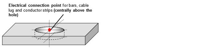
Figure 50: CAx connection example connection point bars
- in the case of bridges/cross-connectors, test probes and similar accessories are maintained in the center of the contact hole. The corresponding contact point on the accessory is positioned so that the components fit together.
Example:
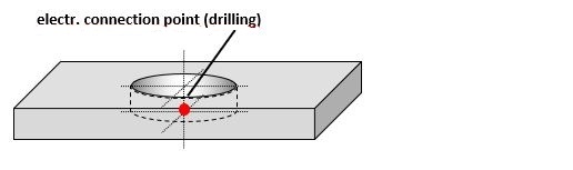
Figure 51: CAx connection example connection point Accessories
- Electrical connection point for bolt connection
- The point lies on the contact surface "down to center of the bolt". The corresponding contact point on the accessory is positioned so that the components fit together.
Example:

Figure 52: CAx connection example connection point bolt
- Electrical connection points of connectors, standard faces (M12, RJ45)
- The points are recorded on the middle of the front of the connectors. The corresponding point of the socket is recorded in such a way that the points match when assembled
Example:
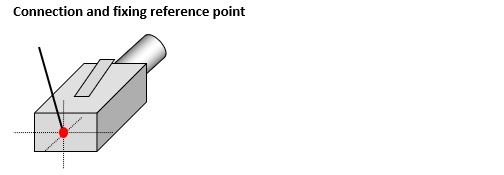
Figure 53: CAx connection Example connection point connector
Operating element of a connection
Mechanical actuation points for screws etc. are characterized by the features: Actuation vector
Tightening torque and output size described. Their physical position is displayed with the (AXIS 1D data type) and the direction with a unit vector.
- The points are recorded centrally on the contact surface between the actuating element and the tool.
- Example:

Figure 54: CAx connection Example of actuation point at the screw head
- If the point cannot be specified reliable due to the connection equipment or the delivery condition, the center must be specified from where a screwdriver has to move into the equipment in order to achieve the output of the screw head. The points are recorded centrally of the housing above the point of contact between the actuating element and the tool.
- Example:
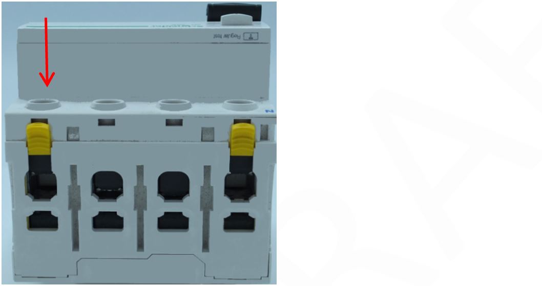
Figure 55: CAx connection Example of actuation point above the screw head at the level of the Housing surface
- Mechanical actuation points for push-in connection

Figure 56: CAx connection Example of actuation point for push-in connection
- Mechanical actuation points for spring balancer connection
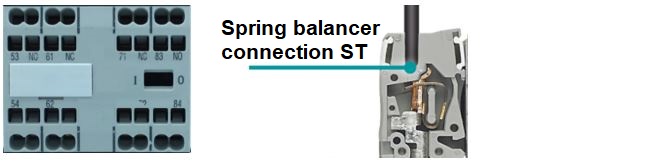
Figure 57: CAxconnection Example of actuation point for spring balancer connection