5.1 How to describe terminals using ECLASS ADVANCED model
Chapter navigation
- Due to their high number of designs and functions, today's "modular terminal blocks" cannot be clearly mapped in circuit diagrams with the existing standards.
- These foils serve to describe the function of the terminals as they are physically constructed.
- On the CAE Tools side, this data can then be mapped to the respective data/structures.

Figure 70: Illustration of the terminals via ECLASS Advanced
Description rule:
- One function per level
- If these are not connected via components (diodes, resistors, ...)
Numbering of connections
- From top to bottom and from left to right in the following order:
- First the wire / plug-in / busbar connections
- Then bridges connections
- For each symbol, the internal and external connections must match the design of the article.
- The symbol shows all fixed and plug-in connections as a line.
- Only the positions of the bridge connections are shown with the number.
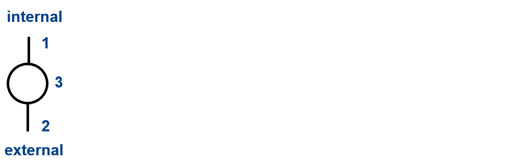
Figure 71: Illustration of the terminals via ECLASS Advanced
- Counting direction of the levels for terminals
- Each level has its own function
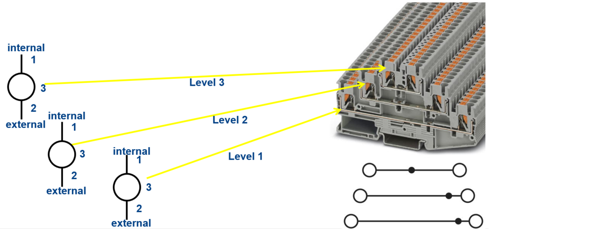
Figure 72: Illustration of the terminals via ECLASS Advanced
- Since terminal connections usually have no designation, numbering of these connections makes sense. First all wire/plug connections and then the bridge connections should be counted.

Figure 73: Function and symbol application examples
- If terminal connections have a designation, this must be used accordingly.
- The labeling of the terminal location is entered in the Connection name field.
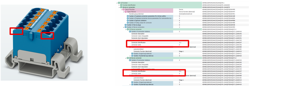
Figure 74: Function and symbol application examples
- For blocked terminals (one order number), each washer has a function
- The level is then always the same
- Counting mode of the connections
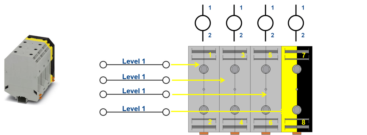
Figure 75: Function and symbol application examples
- For blocked terminals (one order number), each washer has a function
- The level is then always the same
- Counting mode of the connections
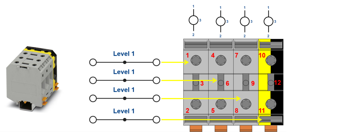
Figure 76: Function and symbol application examples
- The characteristic "Name of potential equivalence" is used to reference further connections with the same potential.
- The connection identifier must be entered in the field, as this is the only way to ensure unambiguous assignment.
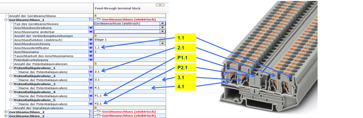
Figure 77: Information on potential equivalence
- For potential distribution terminals that have several levels, a function is specified for each level and referenced to all corresponding connections via the potential equivalence.
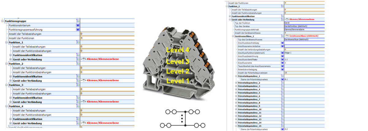
Figure 78: Information on potential equivalence
- The mounting of the clamp on the mounting rail (center top edge of the rail) is described via the mounting reference point.
- If several mounting options are available, the block is often listed as follows
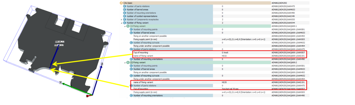
Figure 79: Function and symbol application examples
- The connector must have the same value in the mounting variants as at the terminal in the component holder.
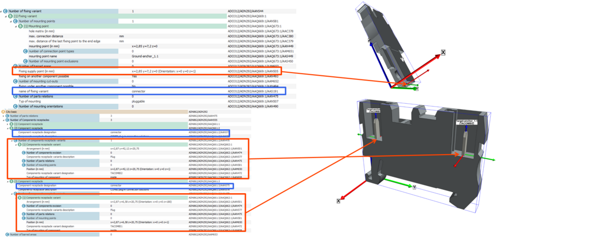
Figure 80: Pluggable terminals
- The plug-in connection at the terminal must be described as a separate electrical connection in the ECLASS model.
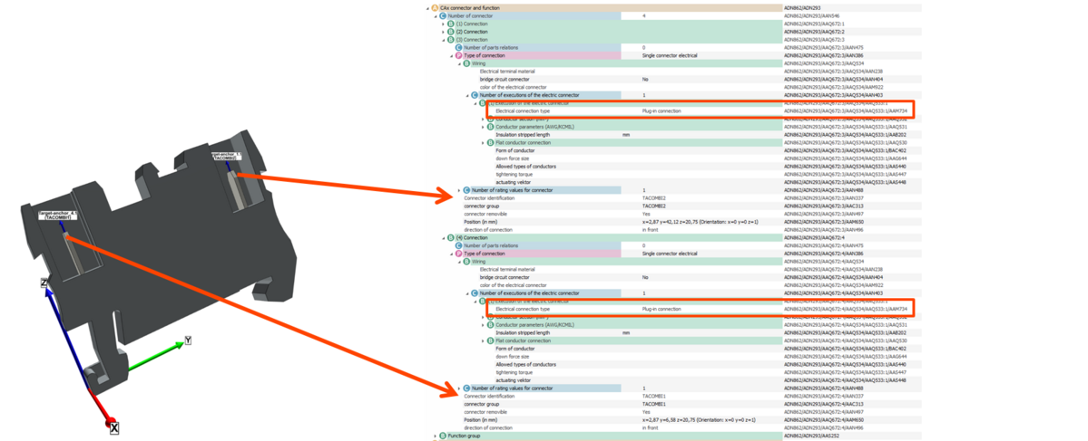
Figure 81: Pluggable terminals
- The potential equivalence indicates to which connections are directly connected
- The signal equivalence indicates which connections are connected when the isolator is closed.
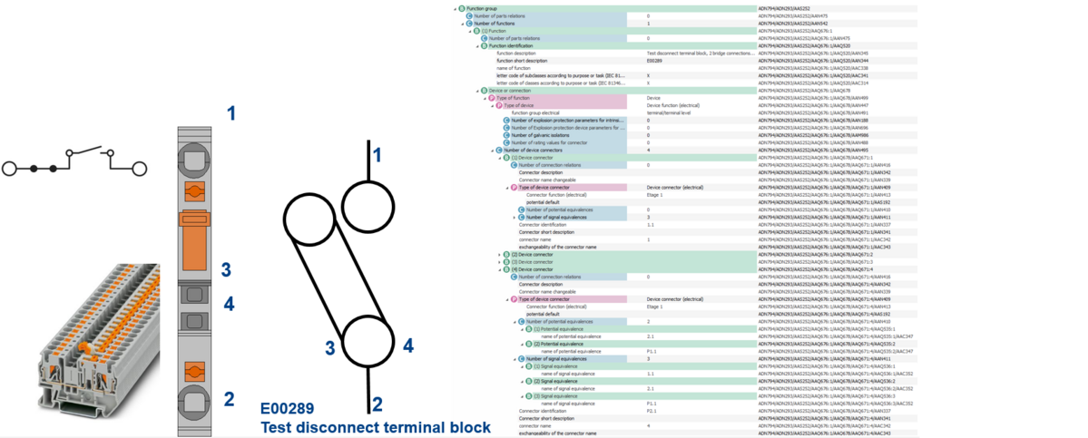
Figure 82: signal equivalence