5.3 Description of heavy-duty connectors (HDC)
Chapter navigation
5.3 Depiction of connectors with the ECLASS CAx model
This chapter describes how to maintain the structures of the ECLASS CAx model so that connector manufacturers can make the data available to the ECAD tools and the target systems can interpret this data accordingly.
Description of the electrical and mechanical properties so that a connector can be assembled in a 3D space and its electrical connections can be mapped in circuit diagrams.

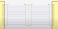
Figure 1: Photo of plug connection and a representation in the circuit diagram
5.3.1 Alignment of reference points and envelopes
To enable correct mechanical assembly in CAD/CAE systems, it is necessary to agree on common rules for the positioning and alignment of anchor points. The anchor points required for assembly are placed according to the following rules using the basic specifications for models in the ECLASS-CAx environment:
- All information refers to the general rules see:
- Specifications for the envelope curve and reference point:
- Regardless of the design (coiled or straight), connectors are described with a cuboid enveloping body
- The foremost plane of the mating face of a circular connector is placed on the surface that spans the X and Y axes
Within the envelope curve, the cable outlet of angled connectors points upwards (12 o'clock)
The reference point of the envelope curve is at the mating face (front end of the connector), the Z-axis points in the direction of the cable connection (rear end of the connector)
For connectors with attached cable, the envelope ends at the end of the connector housing (connector / cable transition
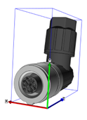
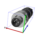
Figure 2: Representation of circular connectors of different designs and the associated shells
5.3.2 Specifications for fixing reference points
- Connectors with female contacts have a target anchor
- Connectors with pin contacts have a base anchor
- The Y axis of the basic anchor/target anchor must be aligned with the PE contact or the lowest identifier. I.e. the PE contact or the lowest identifier is at 12 o'clock. If the PE contact is in the center of rotation of the connector, the contact with the lowest designation (numeric if available, otherwise alphanumeric) can be used. If there is only one FE contact, this is used instead of the PE contact.
- Connectors with female contacts: The Z axis of the target anchor points in the plug-in direction, i.e. towards the mating part. The plane for the target anchor is the upper edge of the O-ring
- Connectors with pin contacts: The Z axis of the base anchor points in the opposite plug-in direction, i.e. towards the cable connection or rear end. The plane for the base anchor is the foremost plane of the mating face.
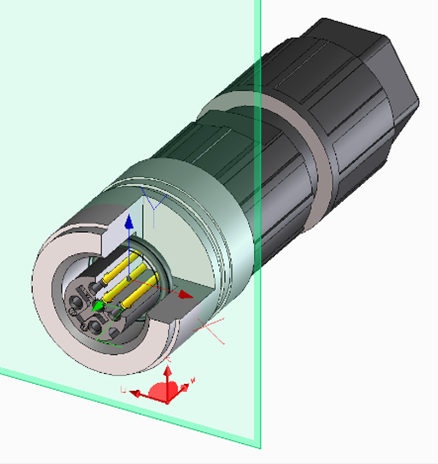
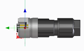
Figure 3: Position of the base and target anchors on circular connectors
5.3.3 Specifications for component receptacle
- The component receptacle blocks are used to describe the points on the product where additional products (accessories, e.g. contact hazard covers, signs, auxiliary switches, triggers) can be attached to extend the function.
- For the connector area, the consistent use of the base and target anchors is essential so that the connectors can be positioned appropriately on the devices.
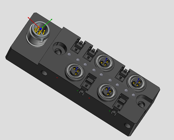
Figure 4: Komponentenaufnahmen für Rundsteckverbindern an einem Gerät
- In the example, the component receptacle for plugs and sockets are available.
- The value of the "name of fixing variant " feature of the fastening variant and the value of the " Components receptacle variant designation" feature must be the same.
- Specifications for contact points
- With ECLASS 15.0, the term chamber has been included in the ECLASS CAx model of the function. The chamber describes a single contact with the socket or plug on one side and the wire or solder connection on the other.
- Corresponding connection identifiers are required for identification
5.3.4 Definiton of name of fixing variant
A standardized representation is required to describe the component mount and mounting variant in the CAx model for the placement of a product on another product. As there may be several different circular plug connections on a sensor/actuator box, for example, the question arises as to how these can be clearly described to enable the correct plug/socket connections.
To clearly describe different plug faces, the thread size, number of positions and coding (within a standard) must be set to the same value to recognize whether the connection works mechanically.
As equating the properties is not available in the various ECAD tools, this should be made possible using a defined text string.
The definition of the description should contain the thread size, the number of pols and the coding. An optional extension of the manufacturer (with 3-digit specification based on ECAD tools) is possible. A manufacturer-specific identifier can also be added.
| Mandatory information | For extension: | |||
| Thread size | Number of pols | Coding | Manufacturer code | Manufacturer-specific identifier |
| M12, M8, … | 3, 4, 5, 8, … | A, B, D, L, T, X, … | always 3 digits | ABC123 |
„-„ - Separators for the mandatory information are
„--„ - Separator for the optional specification
Example:
M12-8-A
M8-3-A
M12-5-X--PXC-ABC123
The following product shows the values to be used on the component receptacles for the circular connector. The user can then place the circular connectors with the corresponding values there.
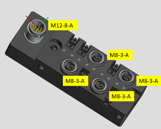
Figure 5: Component receptacles for circular connectors with the corresponding identifiers
5.3.5 Description of Heavy-Duty Connector (HDC)
Today, the product portfolio of heavy-duty connectors essentially consists of individual products from which the user can put together a connector solution according to his requirements.
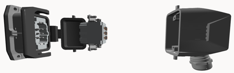
Figure 6: Example of a connector solution consisting of several individual components
For the selection of suitable products for a solution, the manufacturers offer corresponding applications that support the user in the search for a solution. This description serves to support the Figure 6 of a solution for a connector, e.g. from a manufacturer-specific configurator, in an ECAD tool and its assembly in a 2D/3D space.
The classes required to describe the products have been defined in ECLASS area 27-44-02 Connector component.
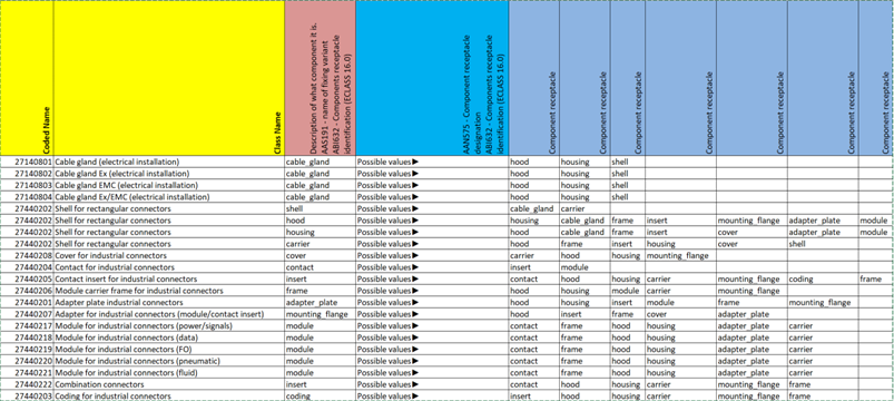
The table shows how the respective components of a plug connection can be combined. To assemble the individual components, the component holder blocks are taken from the ECLASS model:
Link components receptacle: 3.3 Components Receptacles
Link fixing variant: 3.2 Fixing Variants
The list reflects the logical connection for assembly from both directions and defines for each component which other components it can accommodate.
The table (Figure 7) lists the values that have been developed for assembling the heavy-duty connectors. The use of these values is recommended for the following features to support applicability in data exchange and target applications.
AAS191 – Befestigungsvariantenname | name of fixing variant
AAN472 - Bezeichnung der Komponentenaufnahmevariante | Components receptacle variant designation
ABI632 – Komponentenaufnahmeidentifikator | Components receptacle identification (from ECLASS 16.0)
| Values | Description (EN, DE) |
|---|---|
| adapter_plate | Target anchor for holding an adapter plate Zielanker für die Aufnahme von einer Adapterplatte |
| cable_gland | Target anchor for holding a cable gland Zielanker für die Aufnahme von einer Kabelverschraubung |
| carrier | Target anchor for holding a carrier housing Zielanker für die Aufnahme von einem Trägergehäuse |
| coding | Target anchor for holding a coding element Zielanker für die Aufnahme von einem Kodierelement |
| contact | Target anchor for holding a contact (e.g. crimp contact) Zielanker für die Aufnahme von einem Kontakt (z.B. Crimpkontakt) |
| cover | Target anchor for holding a cover cap Zielanker für die Aufnahme von einer Abdeckkappe |
| frame | Target anchor for holding a module carrier frame/frame Zielanker für die Aufnahme von einem Modulträgerrahmen/Rahmen |
| hood | Target anchor for holding an upper housing part (sleeve housing) Zielanker für die Aufnahme von einem Gehäuseoberteil (Tüllengehäuse) |
| housing | Target anchor for holding a lower housing part (panel-mount base, surface mounting housing, coupling housing, feed-through housing) Zielanker für die Aufnahme von einem Gehäuseunterteil (Anbaugehäuse, Sockelgehäuse, Kupplungsgehäuse, Durchführungsgehäuse) |
| insert | Target anchor for holding a contact insert Zielanker für die Aufnahme von einem Kontakteinsatz |
| module | Target anchor for holding a module Zielanker für die Aufnahme von einem Modul |
| mounting_flange | Target anchor for holding a panel-mount flange Zielanker für die Aufnahme von einem Anbauflansch |
| shell | Target anchor for holding a cover Zielanker für die Aufnahme von einer Haube |
| shielding | Target anchor for holding a shielding element Zielanker für die Aufnahme von einem Schirmelement |
Figure 8: Table Overview of the values for the component receptacle variant designation and name of fixing variant
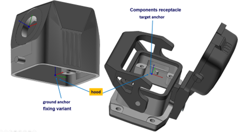
Figure 9: Example of assembly
The solution shown in figure 9 consists of five individual components. To assemble the two housing parts, the grommet housing (hood) must be placed on the panel-mount base (housing). To do this, there must be a target anchor on the panel-mount base for the position in the component holder and a base anchor on the grommet housing for the fastening reference point.
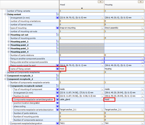
Figure 10: Representation of ECLASS structures in the CAx aspect
Figure 10 shows the two blocks in the CAx Basic aspect of the two housing parts with the assigned values. As shown in the table in Figure 10, the value “hood” is assigned to both features, thus creating a correlation between the two components using the same identifier.