3.1 General Rules
Chapter navigation
3.1.1 General rules ECLASS coordinate system
Orientation
The 3D model must be oriented as in chapter 2.1 General rules for dimensions and directions defined (model orientation = ECLASS orientation).
Origin
The origin of the 3D coordinate system must be on the position of the origin of the model based on dimensions in mounted case (model origin = ECLASS origin).
3.1.2 Rotation angle

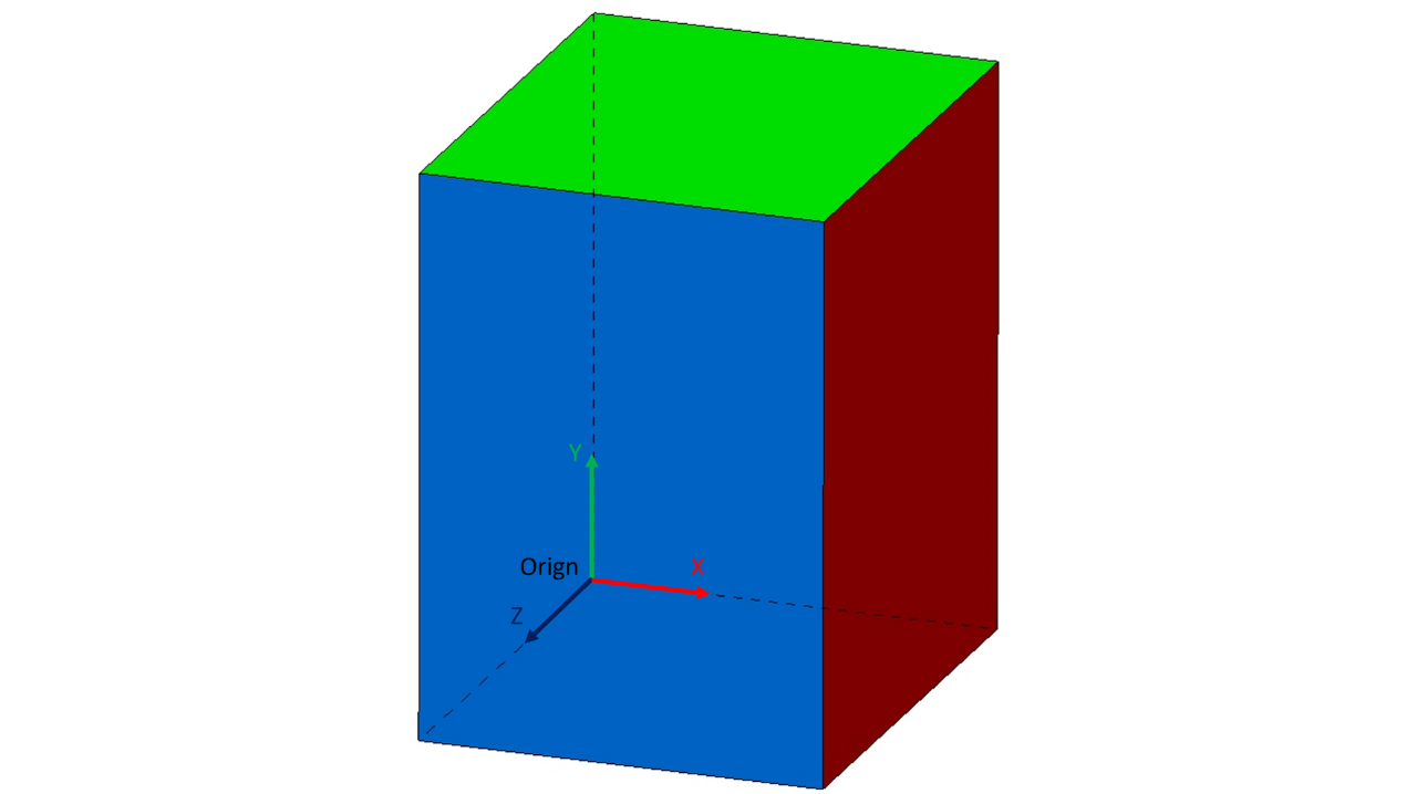
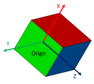
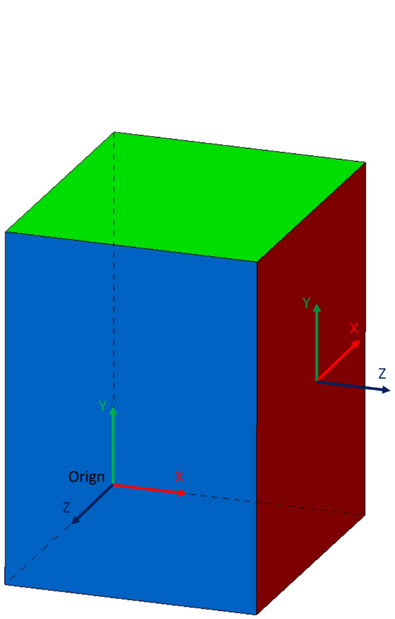
The coordinate cube will be used to illustrate the coordinate axis with rotations include leading signs. Each axis shows the leading sign of the rotation around this axis. Positive signs are shown with plus (+), negative signs with minus (-). With a look from positive axis to coordinate origin, positive rotation will be in counter clocker wise rotation.
The picture shows the coordinate cube placed like ECLASS coordinate system with x- and y-axis placed on surface. In coordinate cube rotation A represents ɣ in Euler-matrix, B represents β and C represents α.
Rotations in one axis
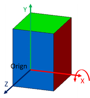
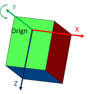
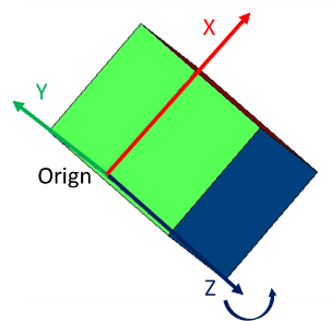
Original orientation | Rotation around x-axis in positive rotation direction | Rotation around y-axis in positive rotation direction | Rotation around z-axis in positive rotation direction |
|
|
|
|
| Following this angle will be named as ɣ related to the use in Euler-matrix. | Following this angle will be named as β related to the use in Euler-matrix. | Following this angle will be named as α related to the use in Euler-matrix. |


Example for a rotation in all 3 axes
First: 45° rotation around x-axis in positive rotation direction | Second: 45° rotation around y-axis in positive rotation direction | Last: 45° rotation around z-axis in positive rotation direction | End position |
3.1.3 General rules for position and direction
ECLASS describes vectors as axis 1D datatype with position and direction according to ISO 10303-42:2000 used in STEP and IFC too.
Example properties for the usage of position and direction:
ID | Name | Description |
AAM650 | Position (in mm) | Coordinate point information (in mm) |
AAN505 | Fixing supply point (in mm) | indicates the reference point for the attachment (in mm) |
AAN449 | mounting point (in mm) | Information of the coordinate of the attachment point (in mm) |
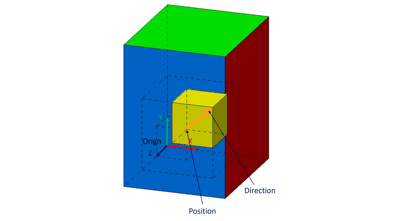
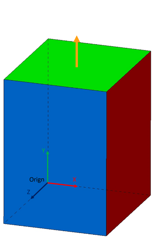
Following example with connector on top (yellow colored)
Size of cuboid: 30 x 60 x 30 mm (W x H x D)
Position of vector: 15 / 60 / 15 mm (x / y / z)
Direction of vector: y-axis
Result is a vector in z-direction rotated around x-axis by -90° (clockerwise)
Axis1D-value:
Attribute | Value |
x-shift | 15 |
y-shift | 60 |
z-shift | 15 |
Orientation ẑx | 0 |
Orientation ẑy | 1 |
Orientation ẑz | 0 |
Very often instead of a vector a coordinate system will be used in CAD tools. In that case the coordinate system needs to be placed that z axis represents the vector and the rotation of the coordinate system is minimized according to origin.

Related coordinate system for the example:
Attribute | Value |
x-shift | 15 |
y-shift | 60 |
z-shift | 15 |
Orientation | 1 |
Orientation | 0 |
Orientation | 0 |
Orientation ŷx | 0 |
Orientation ŷy | 0 |
Orientation ŷz | -1 |
Orientation ẑx | 0 |
Orientation ẑy | 1 |
Orientation ẑz | 0 |
 x
x3.1.4 General rules for position and rotation
In addition to position and direction ECLASS describes vectors as axis 1D datatype with position and rotation.
Example property for the usage of position and rotation:
ID | Name | Description |
AAN501 | Arrangement (in mm) | Orientation of an object in relation to a defined coordinate system, at the join point, both coordinate systems are superimposed by rotating the coordinate system around the x, y- and z- axes, sequence first x then y then z |
Without any rotation the vector represents the z axis of the origin.
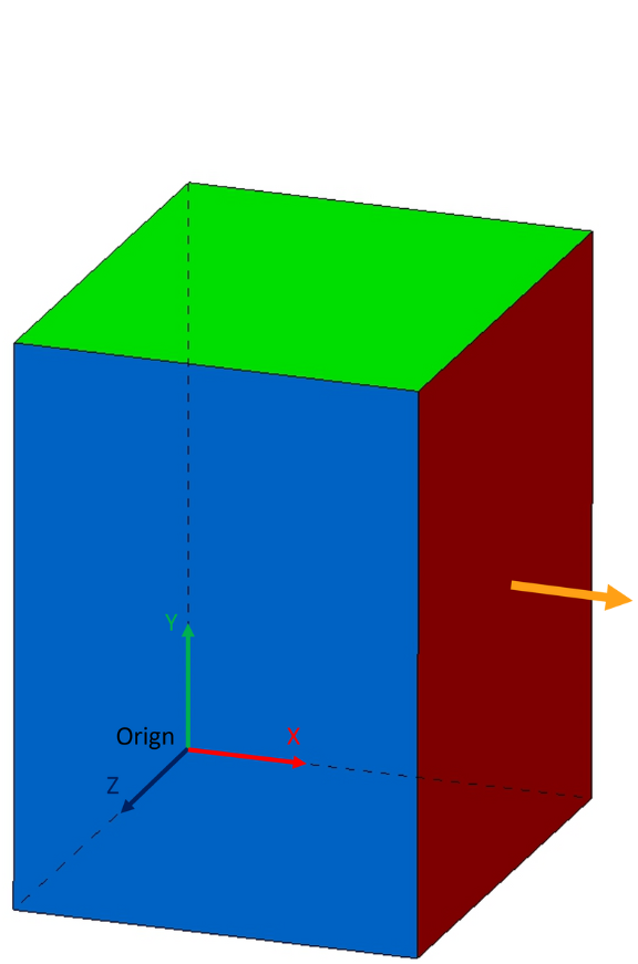
Following example for position with rotation: arrangement on right side for an auxiliary block beside
Size of cuboid: 30 x 60 x 30 mm (W x H x D)
Position of vector: 30 / 30 / 15 mm (x / y / z)
Direction of vector: x-axis
Result is a vector in x-direction rotated around y-axis by 90° (counter clockerwise)
Axis1D-value:
Attribute | Value |
x-shift | 30 |
y-shift | 30 |
z-shift | 15 |
Rotation around x axis: γ | 0° |
Rotation around y axis: β | 90° |
Rotation around z axis: α | 0° |
Very often instead of a vector a coordinate system will be used in CAD tools. In that case the coordinate system needs to be placed that z axis represents the vector and the rotation of the coordinate system is minimized according to origin.
Related coordinate system for the example (values are the same):
Attribute | Value |
x-shift | 30 |
y-shift | 30 |
z-shift | 15 |
Rotation around x axis: γ | 0° |
Rotation around y axis: β | 90° |
Rotation around z axis: α | 0° |
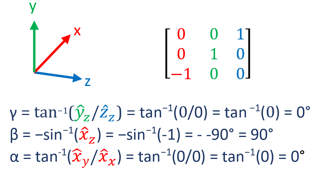
3.1.5 Transformation between direction and rotation
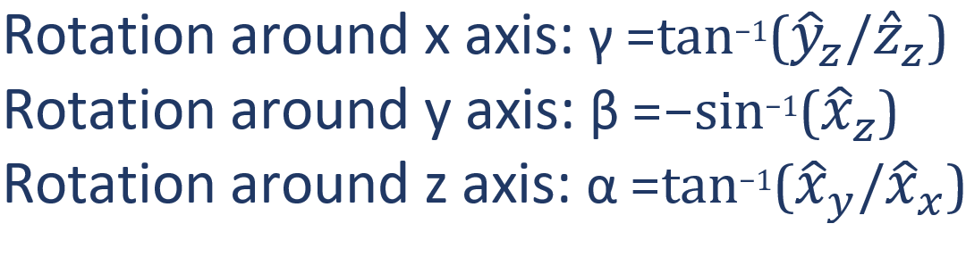
Direction and rotation could be converted between each other via Euler matrix:

Convertion from directions to rotations:
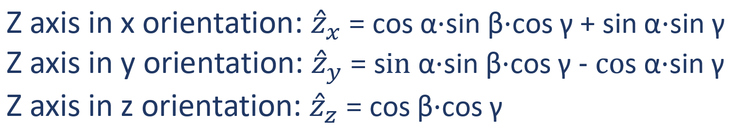
Convertion from rotations to directions:
Example with connector on top
Size of cuboid: 30 x 60 x 30 mm (W x H x D)
Position of vector: 15 / 60 / 15 mm (x / y / z)
Direction of vector: y-axis
Result is a vector in z-direction rotated around x-axis by -90° (clockerwise)

Vector with position and direction:
Attribute | Value |
x-shift | 15 |
y-shift | 60 |
z-shift | 15 |
Orientation ẑx | 0 |
Orientation ẑy | 1 |
Orientation ẑz | 0 |
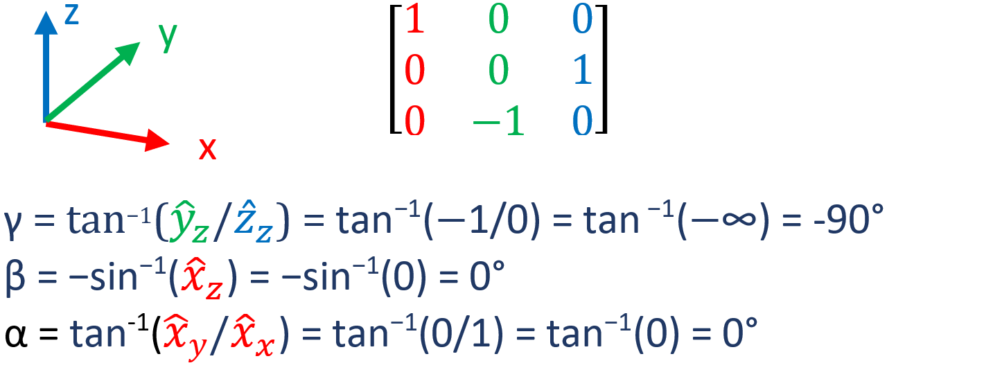
Calculation of rotation with direction as source:
Precondition: create full rotation matrix for 3D object
Calculation of directions with rotation as source:
ẑx = cos α⋅sin β⋅cos γ + sin α⋅sin γ = cos 0°⋅sin 0°⋅cos -90° + sin 0°⋅sin -90° = 1⋅0⋅0 + 0⋅-1 = 0
ẑy = sin α⋅sin β⋅cos γ - cos α⋅sin γ = sin 0°⋅sin 0°⋅cos -90° - cos 0°⋅sin -90  = 0⋅0⋅0 - 1⋅-1 = 1
ẑz = cos β⋅cos γ = cos 0°⋅cos -90° = 1⋅0 = 0
Example with arrangement for auxiliary block beside
Example for position with rotation: arrangement on right side for an auxiliary block beside
Size of cuboid: 30 x 60 x 30 mm (W x H x D)
Position of vector: 30 / 30 / 15 mm (x / y / z)
Direction of vector: x-axis
Result is a vector in x-direction rotated around y-axis by 90° (counter clockerwise)

Axis1D-value:
Attribute | Value |
x-shift | 30 |
y-shift | 30 |
z-shift | 15 |
Rotation around x axis: γ | 0° |
Rotation around y axis: β | 90° |
Rotation around z axis: α | 0° |
Calculation of directions with rotation as source:
ẑx = cos α⋅sin β⋅cos γ + sin α⋅sin γ = cos 0°⋅sin 90°⋅cos 0° + sin 0°⋅sin 90° = 1⋅1⋅1 + 0⋅1 = 1
ẑy = sin α⋅sin β⋅cos γ - cos α⋅sin γ = sin 0°⋅sin 90°⋅cos 0° - cos 0°⋅sin 0  = 0⋅1⋅1 - 1⋅0 = 0
ẑz = cos β⋅cos γ = cos 90°⋅cos 0° = 0⋅1 = 0
Calculation of rotation with direction as source:
Precondition: create full rotation matrix for 3D object
3.1.6 Interaction between component mounts and fastening reference points
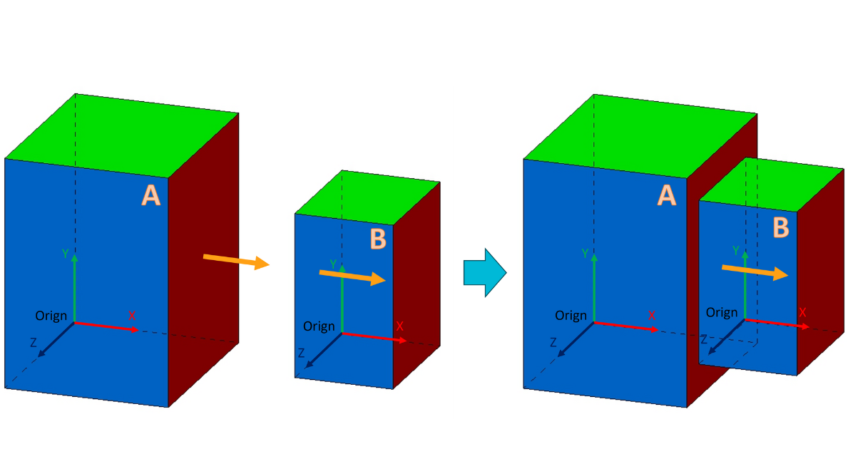
In most of the cases in ECLASS vectors describe information without interaction between 2 vectors.
Exception is the interaction between fixing supply point and the position of a component receptable. Two products are mounted in a way that the fixing supply point of product B is mounted on the position of a component receptable of product A.
Both vectors need to be defined that both vectors are congruent (shows in the same direction). Following picture shows how it works.

If coordinate systems are used in creation, both coordinate systems should be congruent (same rule). Example with using of coordinate systems.